When the forum got rolled back a week this thread disappeared. For some that may have been a good thing, but for others it was a bad thing. So without further adieu I'm starting it back up again. One difference though: flaming, trolling, and thread hijacks will be immediately reported to the mods. ")
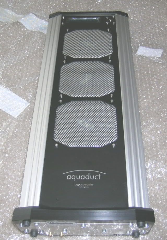
I know I have been interested in seeing the new AC Aquaduct so I suppose perhaps others might as well. It took a while to get the moula up as these go for about $550 here in the states (colonies for you brits), but I have one now. Now most people want to stick it into their rig to see how well it works. Since I take the road less traveled my first thought is to take it apart and do some modding. More on that later. So for now let's see what we get. This monster hunk of German engineering is really quite heavy even without water. I didn't weigh it (scales are bad to have in the house) but it is about 21 lbs (no water) for the main unit.
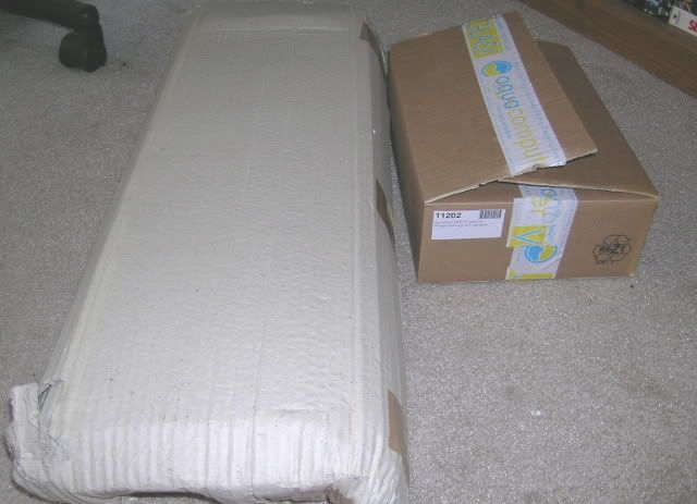
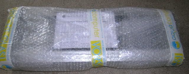
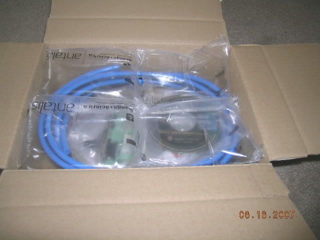
The rest of the stuff comes in the other box and seems to be well packaged for transport around the world.
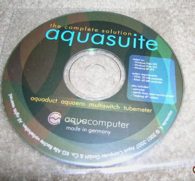
The first item here is the CD that comes in the box. You might not be able to see from the pic, but it has been tested on XP Sp 2; Vista x32, and Vista x64. If you happen to be a penguin fan they also have software for the Linux OS as well. In addition the CD also has Samurize and some videos showing the making of various AC components. One thing to keep in mind is that the software requires version 2 of the .NET framework. If you need software that will run on version 1 there are several back versions of the software you may find usable here at the Aqua Computer site. You can also find version 1 & 2 on the CD as well. One thing I forgot to mention is that the Aquasuite software comes with a Software Development Kit (SDK) that is included on the CD as well for your modding pleasure.
You used to have to run the Aquasuite in the background if you wanted to use Samurize, but now someone has made a hack that allows you to print operating conditions directly to your screen without the Aquasuite being on.
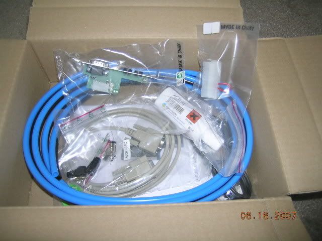
Next you see the rest of the stuff in the box.
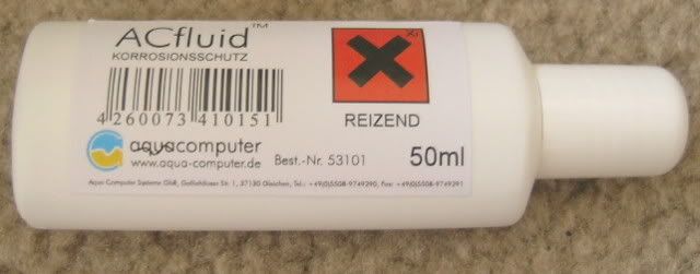
A bottle of AC Fluid. My math calculates about 343 ML of distilled water + 7 cc AC Fluid in my Feeding Frenzy Interlude project. So I figure you can make about 2.5 liters of coolant with this 50 cc bottle. From what I have been told the whole Aquaduct system (including blocks) holds about 2 liters of coolant.
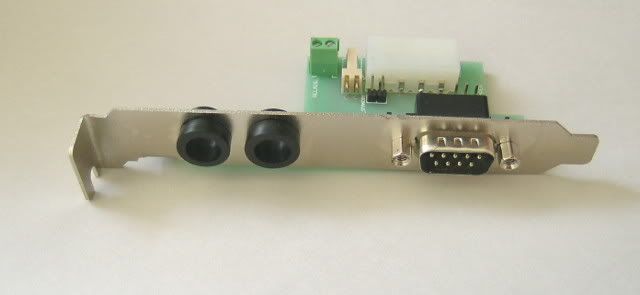
Here the slot device through which the hoses can go through your case into the computer. The serial is not really a serial port, but is used only to carry power to the Aquaduct and for some assorted accessory use in case you want to add standby power or a relay output to your ATX break line.
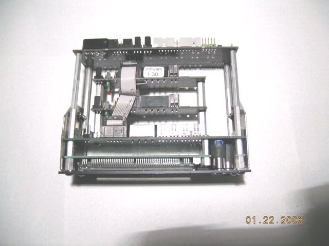
So back to the Aquaduct. Last night I started the disassembly and here I have already taken off the blue plexi top.
One thing that is very important about the un-tightening sequence is that you must use a cross pattern and only a twist or two of the driver per sequence. This will became apparent later on as to the why.
Make sure you bag up the screws as the flat head TORX screws may be hard to find in your locale.
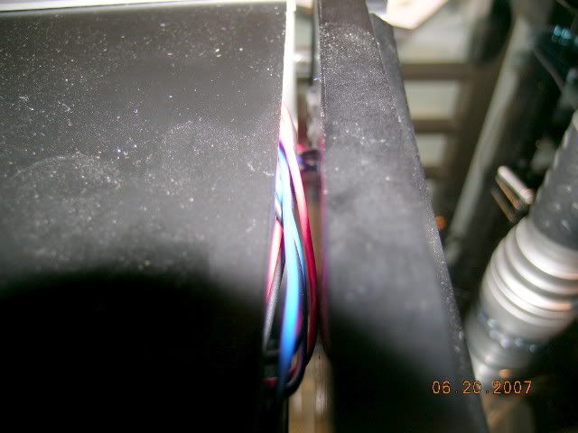
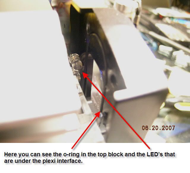
The wires you see here are the important ones to make sure you don't accidentally pull out of the top plate. These are the four (4) LED's that make up the blue glow you see in normal operation. These LED's can also be configured to glow red according to whatever temp you decide should be a visual warning.
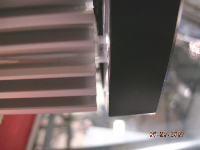
When I first pulled out the top plate a ways I wasn't sure how all this was connected together so I decided to take off the plexi plate that you can see fitted into the top plate. This is totally unnecessary so don't do what I did. However, the plus side is that you get to see more pics, right?
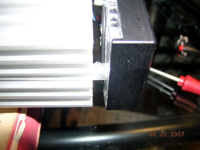
That plexi plate was really difficult to get out. If you decide to take it out you will need some dental probes, some jewelers screwdrivers, and maybe some kind of really thin piece of flat stock about 1.5" wide.
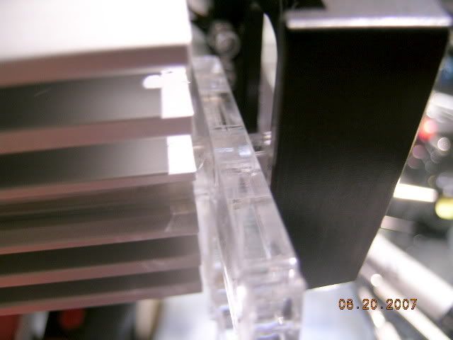
I finally got that dang plate out. Be careful you don't scratch it or you will be FUBAR as two o-rings seal against it.
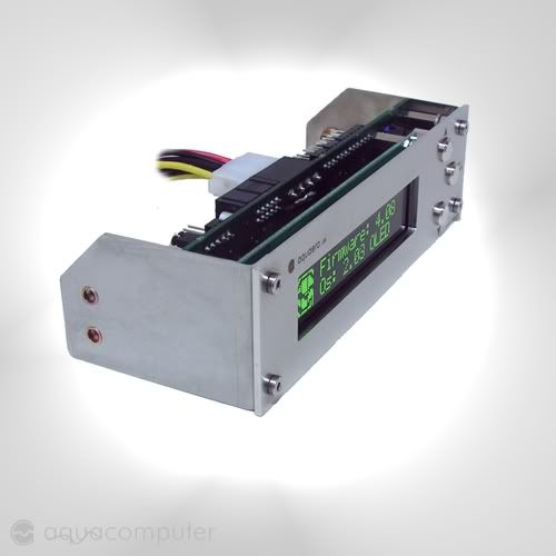
Now that I got the front plate off this is what is underneath it. For those in the know this looks like a pretty standard Aquaero circuit board, except for that big electrolytic capacitor just between the LCD board and the Aquaero board. Notice the sleeving on the fan wires? Now that's class to sleeve when no one will ever see it, huh?
Another odd thing is that you can see that they have the ribbon cable (to the left of the molex power connector) hooked up to something. Wonder what that is because AC has said that the Poweradjust unit can't be interfaced to the Aquaero and there certainly isn't an Aquastream in this Aquaduct. I guess we will see later what the surprise is.
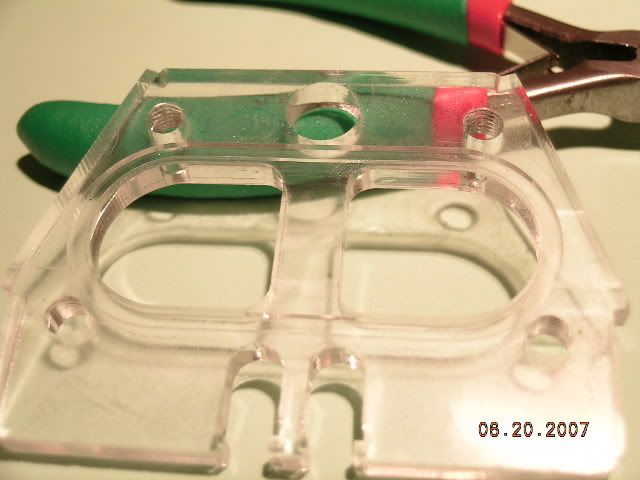
Here is one of the plexi plates. These also have an o-ring groove machined into it so that it seals against the aluminum side cooling extrusions.
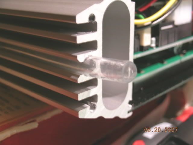
I have been thinking about something here. See that gigantic flow chamber? I wonder how much extra flow you get from having that additional water cross section in the loop. That's 1.890" x 0.710" x about 23" x 2 sides plus the fairly wide water channel in the top plate.
Remember when I suggested that you be very careful when unscrewing the Torx screws. Now you can see why I made the warning. The tapped holes are missing about 20% of their threads so creating a lateral force on the top while taking it off might FUBAR the threads. BTW, I would highly suggest that you cover that surface with some blue painters tape to protect that surface from scratches. O-rings don't like scratches.
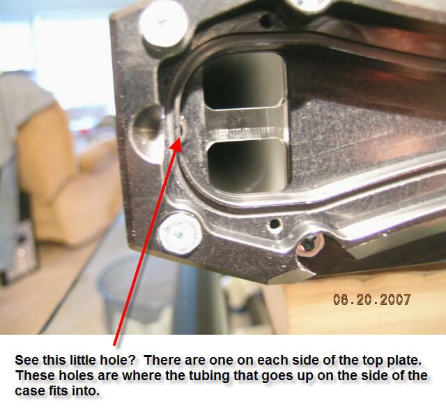
Here's another pic of the top plate. Make sure you don't pull the LED's loose as they fit exactly into the plexi plate shown above.
Hey, we got more cross sectional flow here add in another 6mm x 25" x 2 tubes.
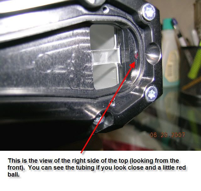
Here's the right side of the top plate. The little red ball only shows flow when you start up the Aquaduct. While it is in operation it sits up here in the top block.
The next job is to slide out the black plate you see at the top of the pic.
That's all for now till I take some more pics.
Okay, time to do some more surgery. The next operation is to get the back panel off. To do this you have to take off all the 3mm fan screws. Two of the screws had the socket hex stripped. Not fun to have to get a pair of vice-grips out to get them off. Well no big deal as I plan on only using stainless button heads on re-assembly. ;D
Here you can see me sliding off the back panel.
In case you were wondering how they did that fancy grill this is it. AC has started selling this grill in some pre-made cases so I think it is only a matter of time before they sell them by themselves.
Here's looking at the bottom inside of the Aquaduct.
Here you can see the Eheim Compact 600 pump and the DigMesa flow meter is barely visible under the tubing on the right side. I take back what I said earlier about their good wiring skills. All these wires are going to have to be customized to the proper length and sleeved. How about a plexi back plate here? 8)
Here is a close-up of the 360 radiator and the temp probe they have placed to measure the air temp after leaving the radiator.
The water tubes go along both sides of the radiator. Seems strange, but I guess we will have to wait till further disassembly to see what's up. The wires also are routed through this area on both sides as well (more sleeving and shortening). Using bigger tubing looks kind of tight in here. Guess I got to order the tubing and see what we see.
The circuit board you see here is the pump controller board and is piggy backed to the Aquaero. In addition it has a ribbon cable to allow control and create a feed back loop to the software/hardware.
More later when I have time to process more pics.
I know I have been interested in seeing the new AC Aquaduct so I suppose perhaps others might as well. It took a while to get the moula up as these go for about $550 here in the states (colonies for you brits), but I have one now. Now most people want to stick it into their rig to see how well it works. Since I take the road less traveled my first thought is to take it apart and do some modding. More on that later. So for now let's see what we get. This monster hunk of German engineering is really quite heavy even without water. I didn't weigh it (scales are bad to have in the house) but it is about 21 lbs (no water) for the main unit.
The rest of the stuff comes in the other box and seems to be well packaged for transport around the world.
The first item here is the CD that comes in the box. You might not be able to see from the pic, but it has been tested on XP Sp 2; Vista x32, and Vista x64. If you happen to be a penguin fan they also have software for the Linux OS as well. In addition the CD also has Samurize and some videos showing the making of various AC components. One thing to keep in mind is that the software requires version 2 of the .NET framework. If you need software that will run on version 1 there are several back versions of the software you may find usable here at the Aqua Computer site. You can also find version 1 & 2 on the CD as well. One thing I forgot to mention is that the Aquasuite software comes with a Software Development Kit (SDK) that is included on the CD as well for your modding pleasure.
You used to have to run the Aquasuite in the background if you wanted to use Samurize, but now someone has made a hack that allows you to print operating conditions directly to your screen without the Aquasuite being on.
Next you see the rest of the stuff in the box.
A bottle of AC Fluid. My math calculates about 343 ML of distilled water + 7 cc AC Fluid in my Feeding Frenzy Interlude project. So I figure you can make about 2.5 liters of coolant with this 50 cc bottle. From what I have been told the whole Aquaduct system (including blocks) holds about 2 liters of coolant.
Here the slot device through which the hoses can go through your case into the computer. The serial is not really a serial port, but is used only to carry power to the Aquaduct and for some assorted accessory use in case you want to add standby power or a relay output to your ATX break line.
So back to the Aquaduct. Last night I started the disassembly and here I have already taken off the blue plexi top.
One thing that is very important about the un-tightening sequence is that you must use a cross pattern and only a twist or two of the driver per sequence. This will became apparent later on as to the why.
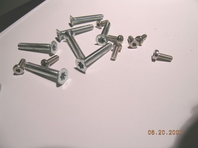
Make sure you bag up the screws as the flat head TORX screws may be hard to find in your locale.
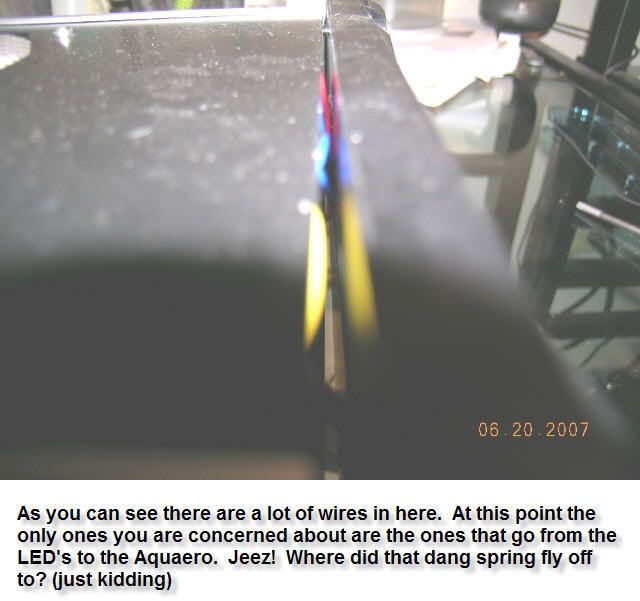
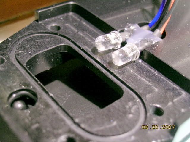
The wires you see here are the important ones to make sure you don't accidentally pull out of the top plate. These are the four (4) LED's that make up the blue glow you see in normal operation. These LED's can also be configured to glow red according to whatever temp you decide should be a visual warning.
When I first pulled out the top plate a ways I wasn't sure how all this was connected together so I decided to take off the plexi plate that you can see fitted into the top plate. This is totally unnecessary so don't do what I did. However, the plus side is that you get to see more pics, right?
That plexi plate was really difficult to get out. If you decide to take it out you will need some dental probes, some jewelers screwdrivers, and maybe some kind of really thin piece of flat stock about 1.5" wide.
I finally got that dang plate out. Be careful you don't scratch it or you will be FUBAR as two o-rings seal against it.
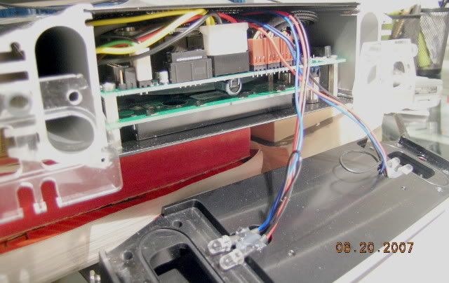
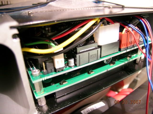
Now that I got the front plate off this is what is underneath it. For those in the know this looks like a pretty standard Aquaero circuit board, except for that big electrolytic capacitor just between the LCD board and the Aquaero board. Notice the sleeving on the fan wires? Now that's class to sleeve when no one will ever see it, huh?
Another odd thing is that you can see that they have the ribbon cable (to the left of the molex power connector) hooked up to something. Wonder what that is because AC has said that the Poweradjust unit can't be interfaced to the Aquaero and there certainly isn't an Aquastream in this Aquaduct. I guess we will see later what the surprise is.
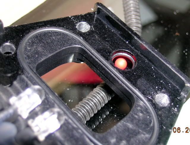
Here is one of the plexi plates. These also have an o-ring groove machined into it so that it seals against the aluminum side cooling extrusions.
I have been thinking about something here. See that gigantic flow chamber? I wonder how much extra flow you get from having that additional water cross section in the loop. That's 1.890" x 0.710" x about 23" x 2 sides plus the fairly wide water channel in the top plate.
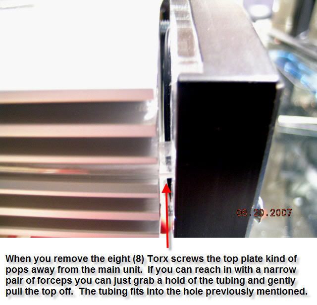
Remember when I suggested that you be very careful when unscrewing the Torx screws. Now you can see why I made the warning. The tapped holes are missing about 20% of their threads so creating a lateral force on the top while taking it off might FUBAR the threads. BTW, I would highly suggest that you cover that surface with some blue painters tape to protect that surface from scratches. O-rings don't like scratches.
Here's another pic of the top plate. Make sure you don't pull the LED's loose as they fit exactly into the plexi plate shown above.
Hey, we got more cross sectional flow here add in another 6mm x 25" x 2 tubes.
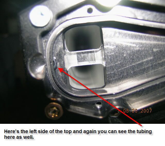
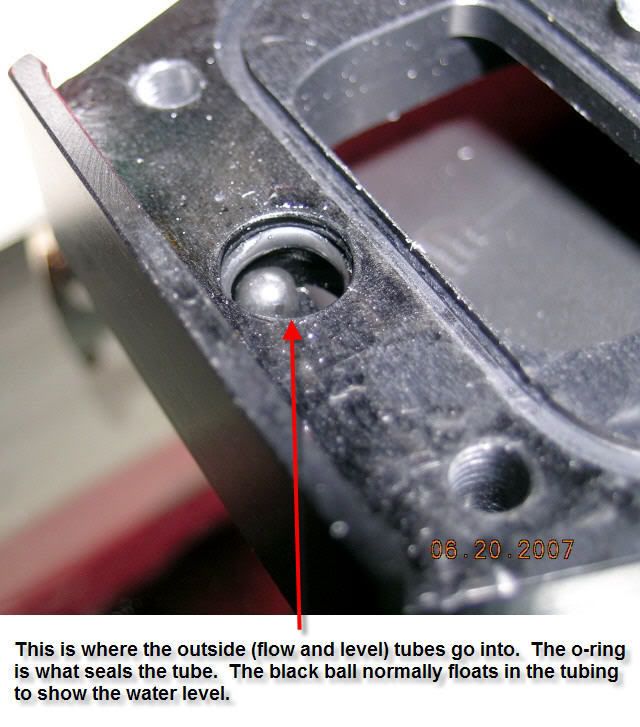
Here's the right side of the top plate. The little red ball only shows flow when you start up the Aquaduct. While it is in operation it sits up here in the top block.
The next job is to slide out the black plate you see at the top of the pic.
That's all for now till I take some more pics.
Okay, time to do some more surgery. The next operation is to get the back panel off. To do this you have to take off all the 3mm fan screws. Two of the screws had the socket hex stripped. Not fun to have to get a pair of vice-grips out to get them off. Well no big deal as I plan on only using stainless button heads on re-assembly. ;D
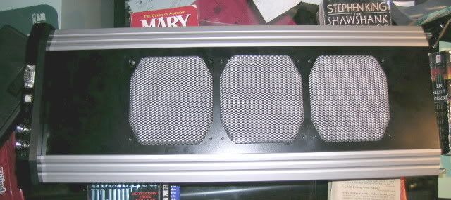
Here you can see me sliding off the back panel.
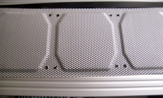
In case you were wondering how they did that fancy grill this is it. AC has started selling this grill in some pre-made cases so I think it is only a matter of time before they sell them by themselves.
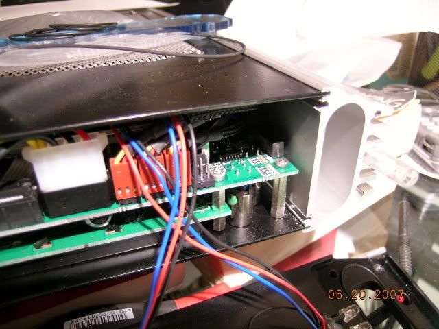
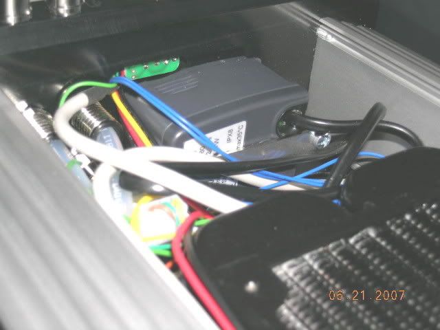
Here's looking at the bottom inside of the Aquaduct.
Here you can see the Eheim Compact 600 pump and the DigMesa flow meter is barely visible under the tubing on the right side. I take back what I said earlier about their good wiring skills. All these wires are going to have to be customized to the proper length and sleeved. How about a plexi back plate here? 8)
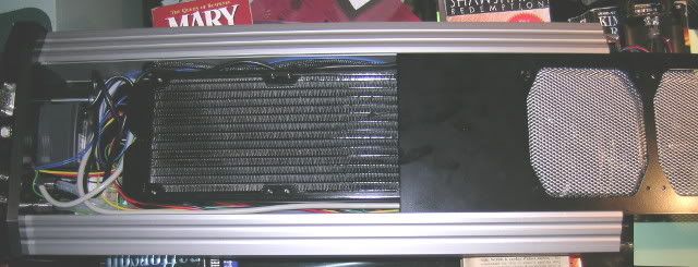
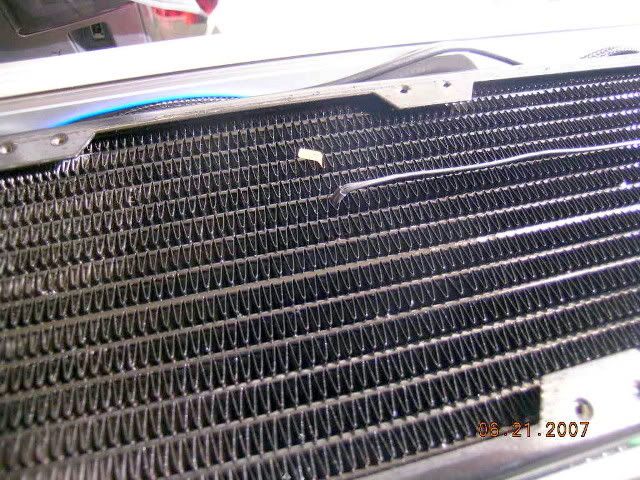
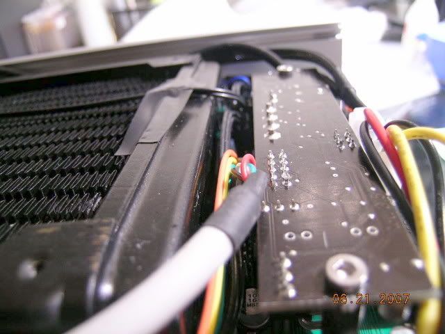
Here is a close-up of the 360 radiator and the temp probe they have placed to measure the air temp after leaving the radiator.
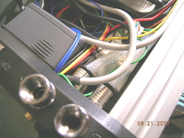
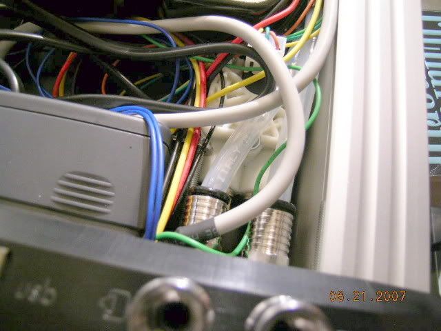
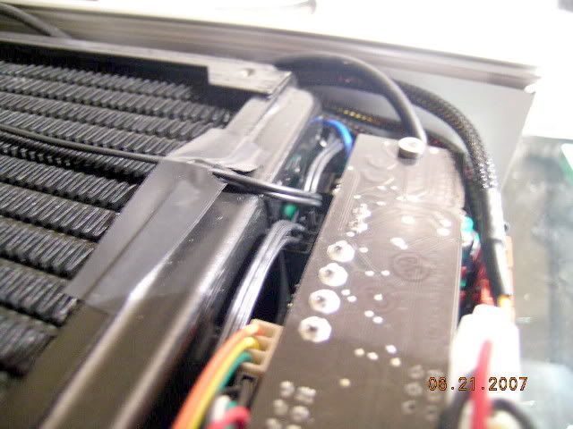
The water tubes go along both sides of the radiator. Seems strange, but I guess we will have to wait till further disassembly to see what's up. The wires also are routed through this area on both sides as well (more sleeving and shortening). Using bigger tubing looks kind of tight in here. Guess I got to order the tubing and see what we see.
The circuit board you see here is the pump controller board and is piggy backed to the Aquaero. In addition it has a ribbon cable to allow control and create a feed back loop to the software/hardware.
More later when I have time to process more pics.