Stevennoland
Limp Gawd
- Joined
- Jan 5, 2006
- Messages
- 418
Hello avid computer users, gamers’, and system modders and builders. I’m back with another work log.
Don’t fret, Beast III isn’t dead. I’ll actually be using some of it for this build. This build will be an update to Beast 2.75; the system I’m currently using.
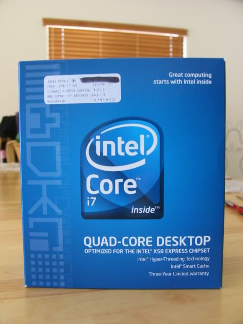
Since Intel released its current speed champ, the i7 series, I knew it was time to upgrade. I had done some research and concluded the 920 proc was the way to go. An X58 mobo was also in order. And to get the best memory performance, 3 x 2GB of 1600 mem (minimum) was also on the menu.
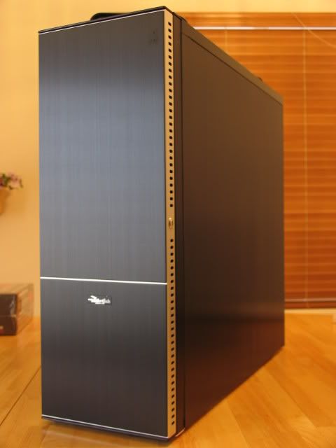
I had a spare Lian-Li / Rocketfish case lying around, so I decided to use it as the backbone. I wanted to water cool as well. I will be using many of the parts from Beast 2.75 for most of the water cooling.
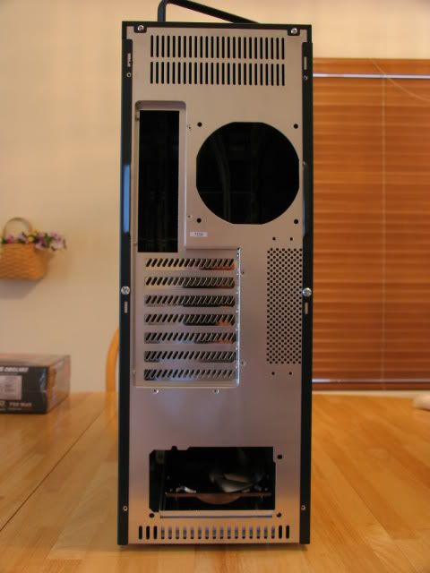
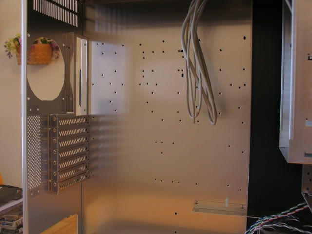
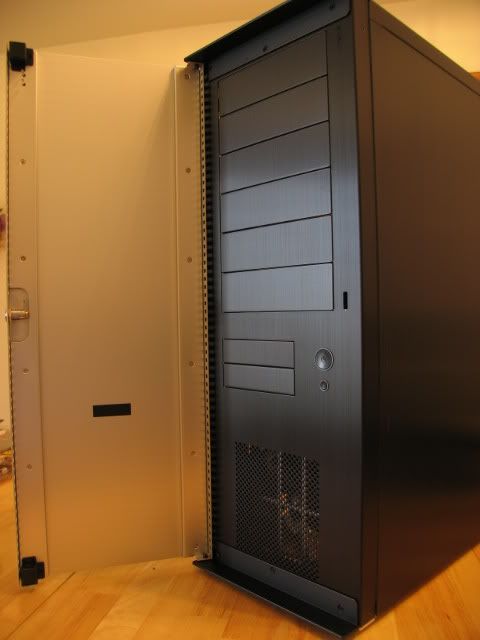
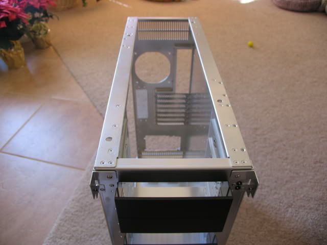
This case is certainly not as well built as some of my other Lian-Li’s, but it does have some features I like. The space at the top above the MOBO section is perfect for a triple rad set-up that is actually located inside the case (unlike Beast 2.75). I can also remove all the HDD cages since I’m planning on using an SSD for the OS and progs. I can also ditch the 3.5” cage since floppies are so out. First, some shots of the case.
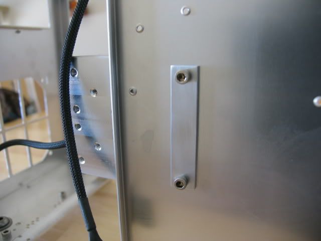
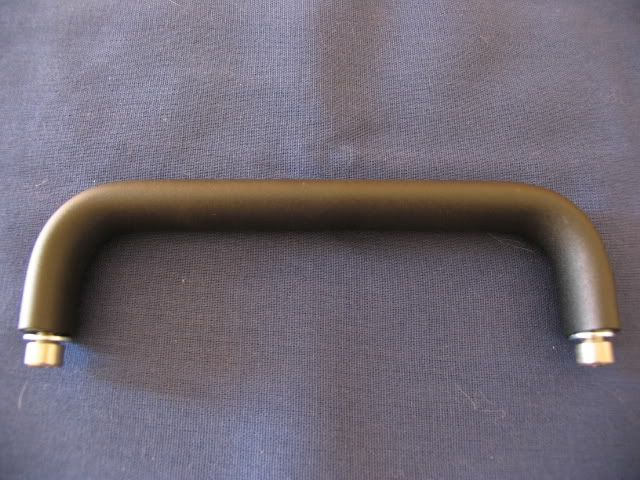
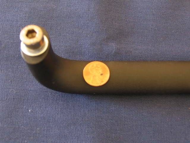
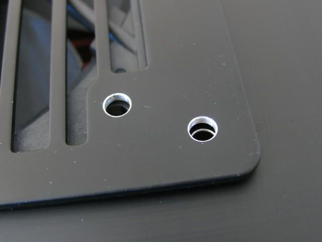
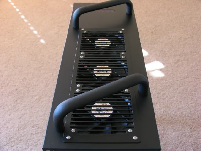
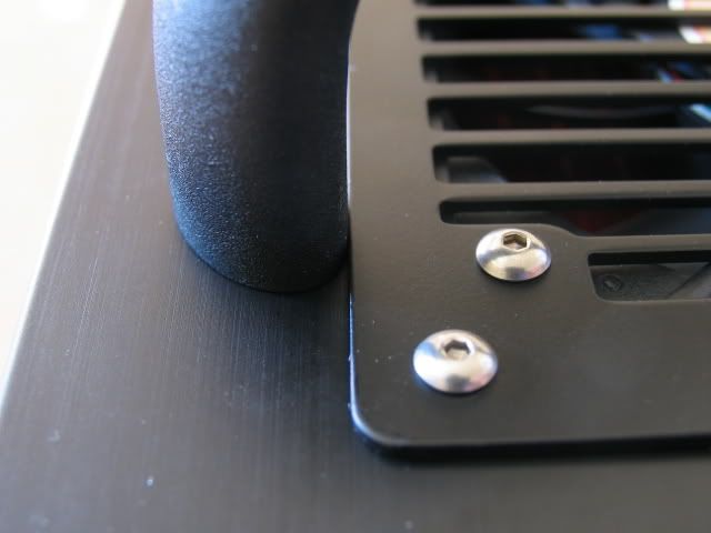
First step was to add some handles (these are the same ones on the doors of the CNC lathes I use at work). These suckers are beefy, and at $20.00 each, they had better be.
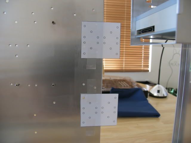
Here is a shot of the holes for the handles
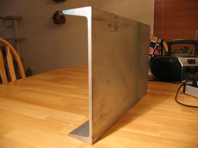
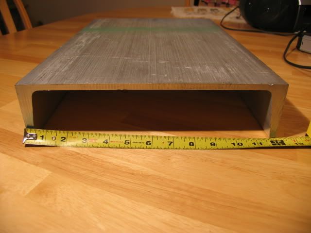
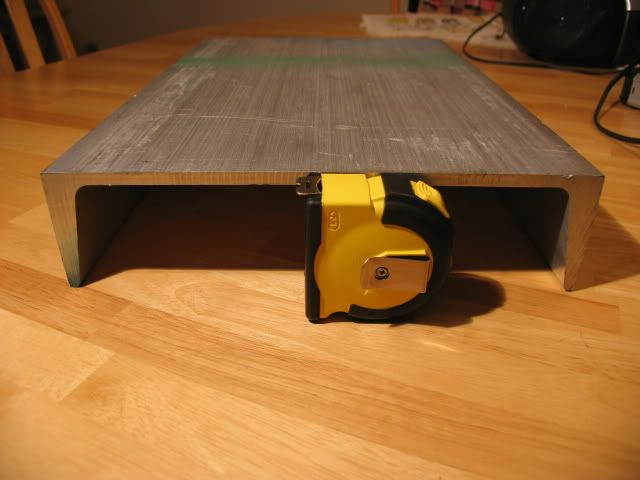
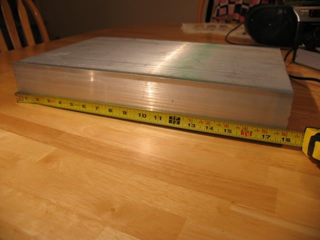
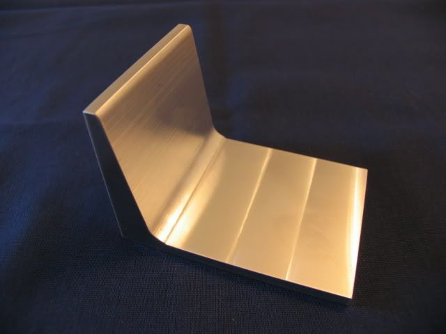
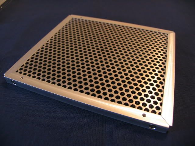
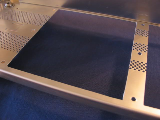
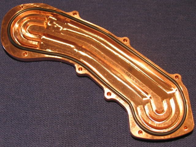
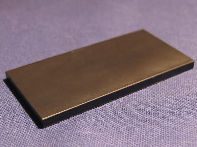
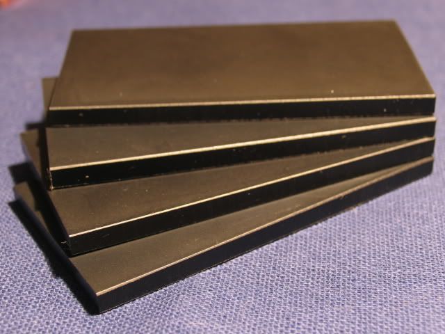
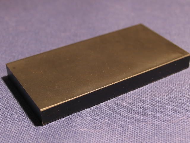
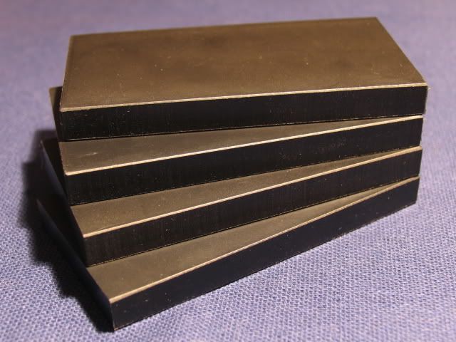
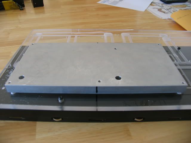
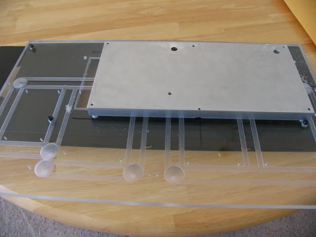
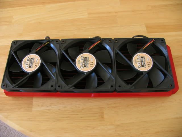
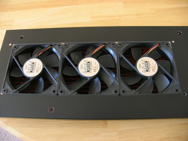
Here are the filters I made for Beast III. Since this case has the space at the bottom, I chose to incorporate them into this build. I also wanted to cut down on the dust intake as much as possible.
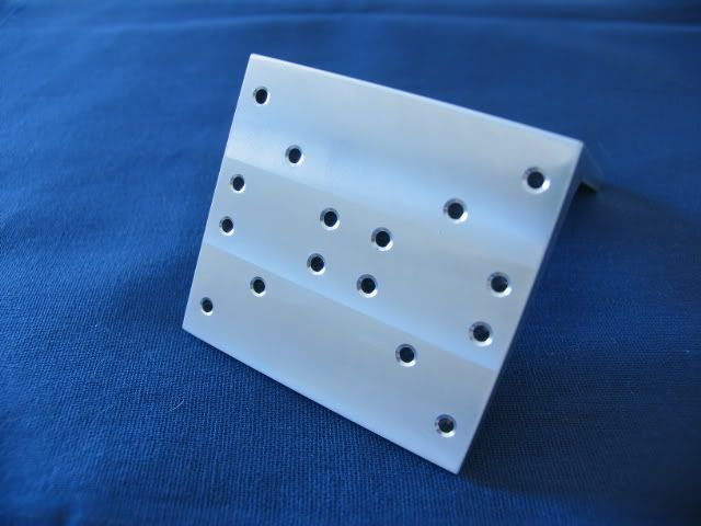
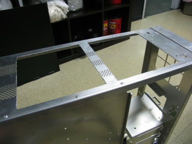
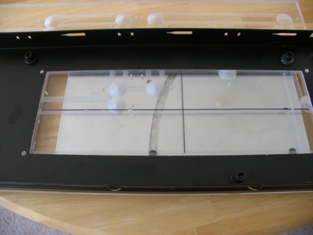
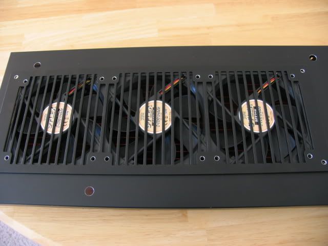
Here are the cut-outs for the air flow. I used my Roto-Zip to rough these out.
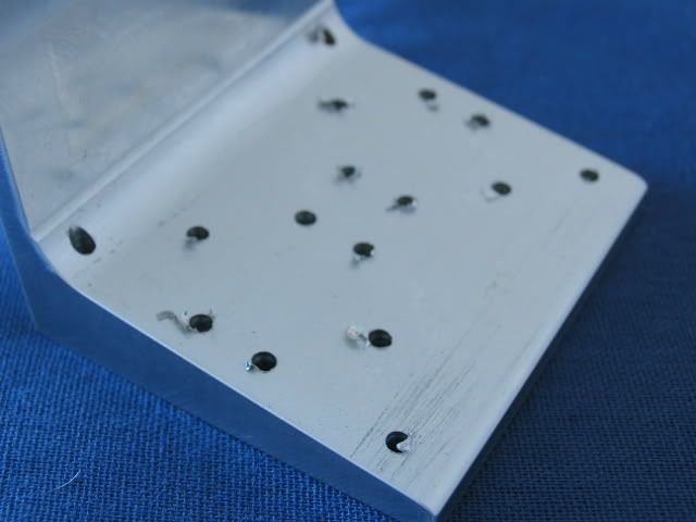
Wicked burrs!
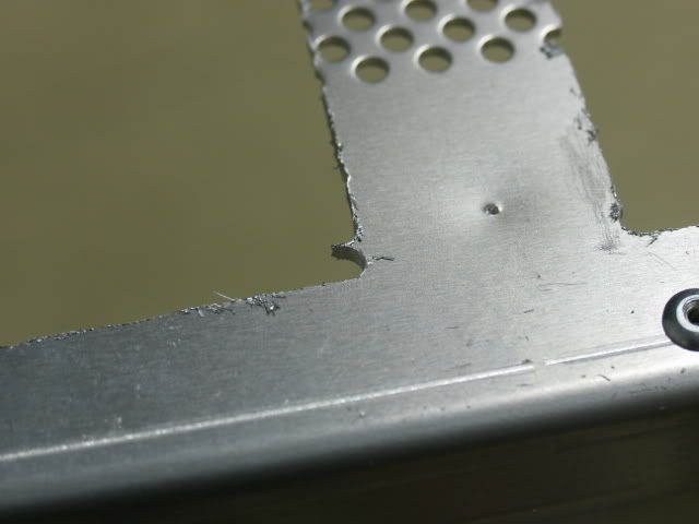
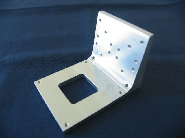
I then filed the edges smooth. Back intake.
Front intake
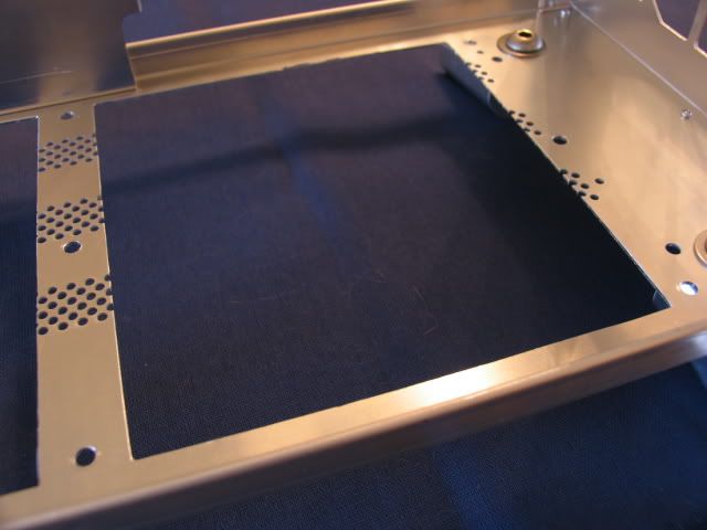
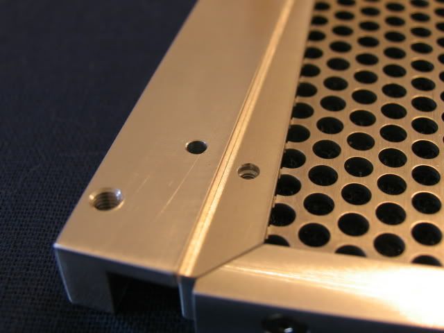
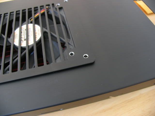
Holes for the rails to hold the filters
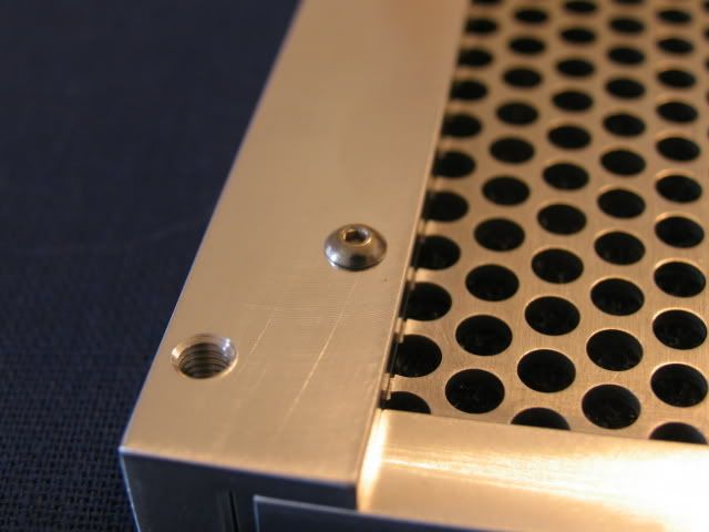
Close fit
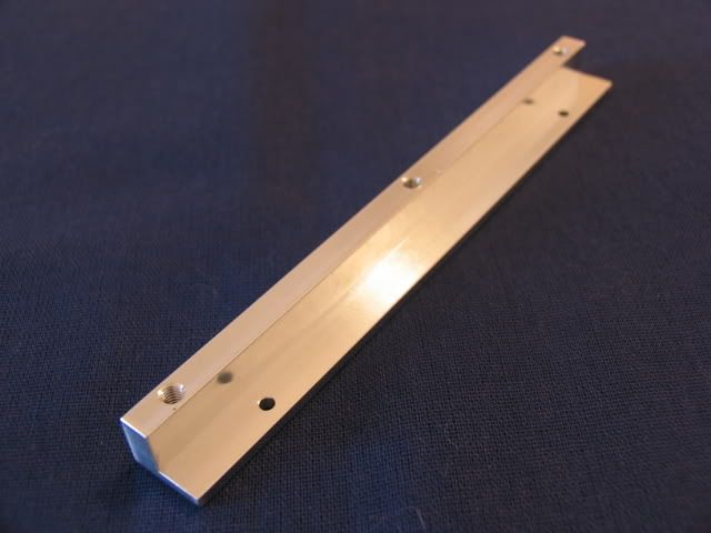
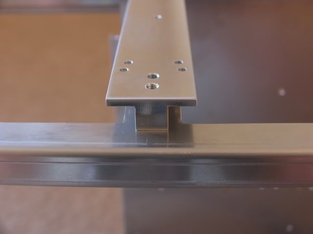
Here is the middle rail. There are two sets of holes because some idiot dimensioned in ‘Paper Space’ instead of ‘Model Space’. If you don’t know the difference, ask someone who uses Auto CAD. Shame on me.
Here are the end rails
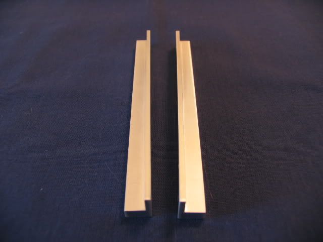
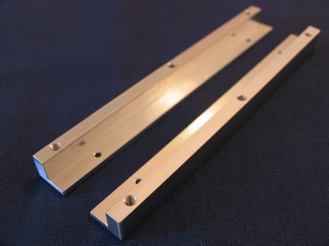
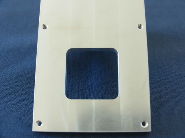
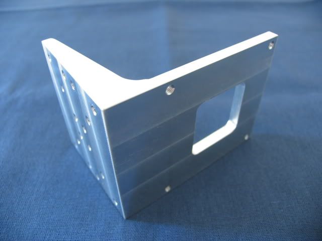
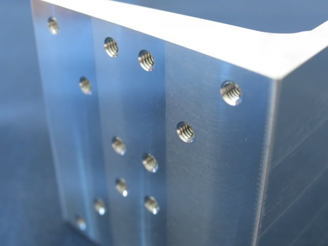
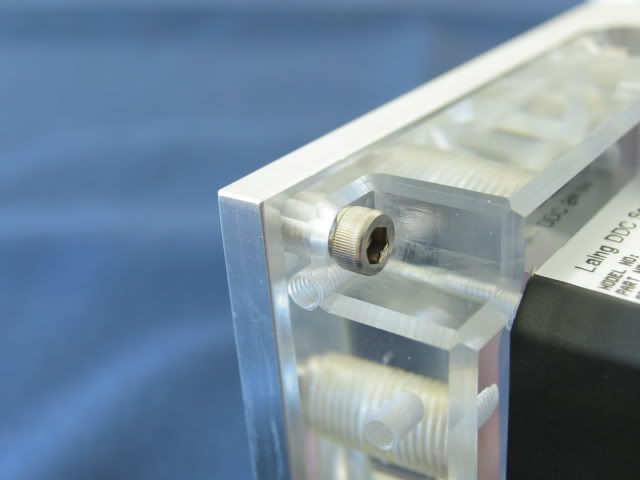
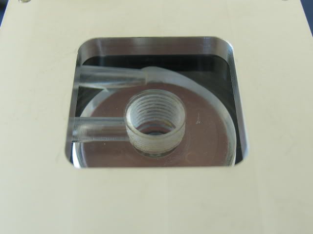
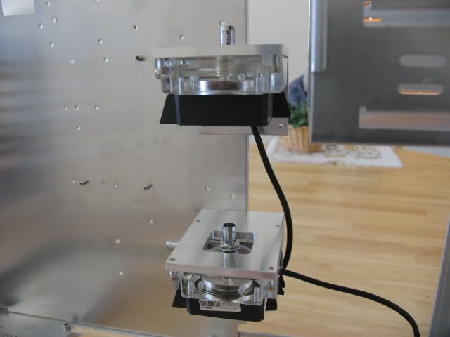
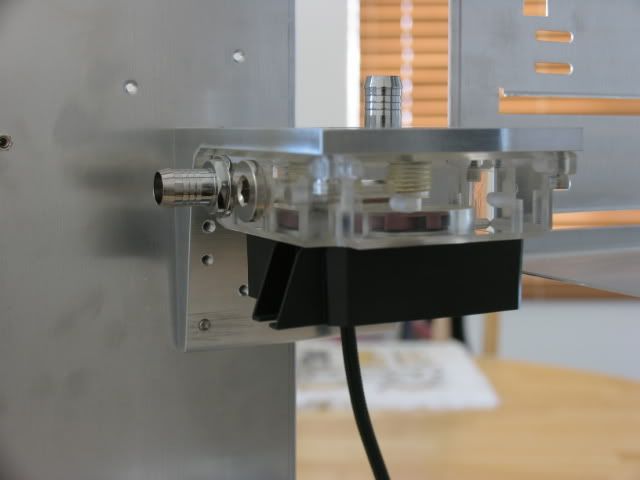
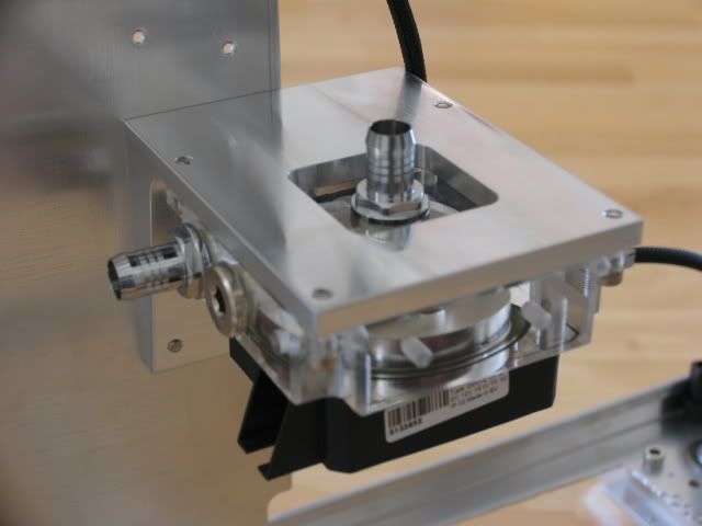
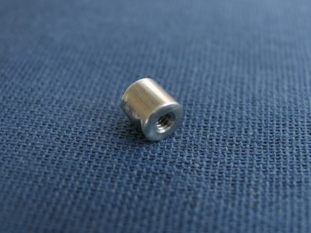
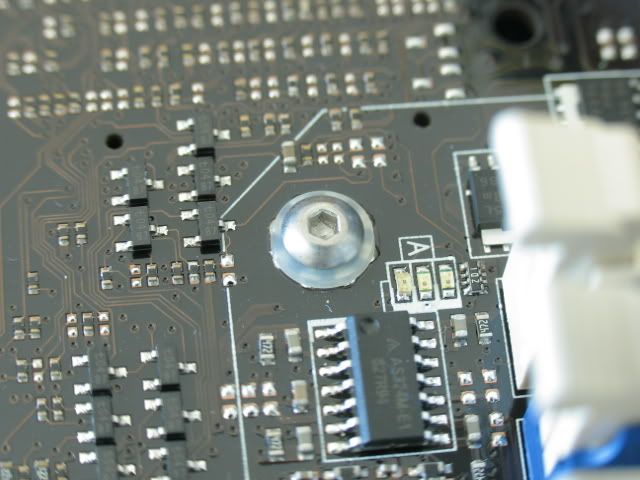
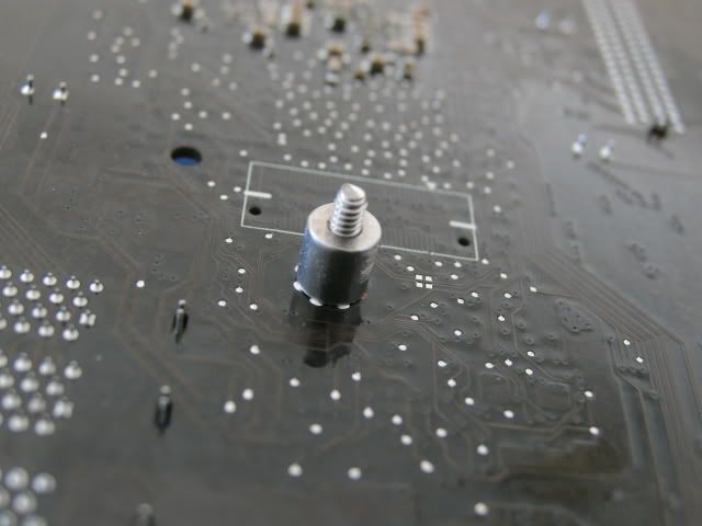
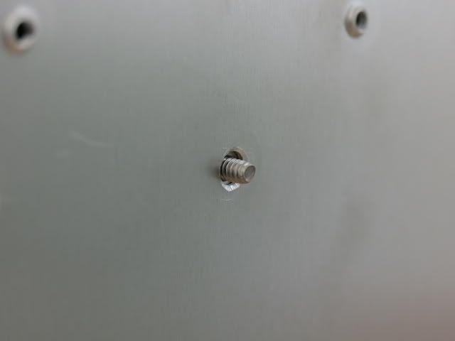
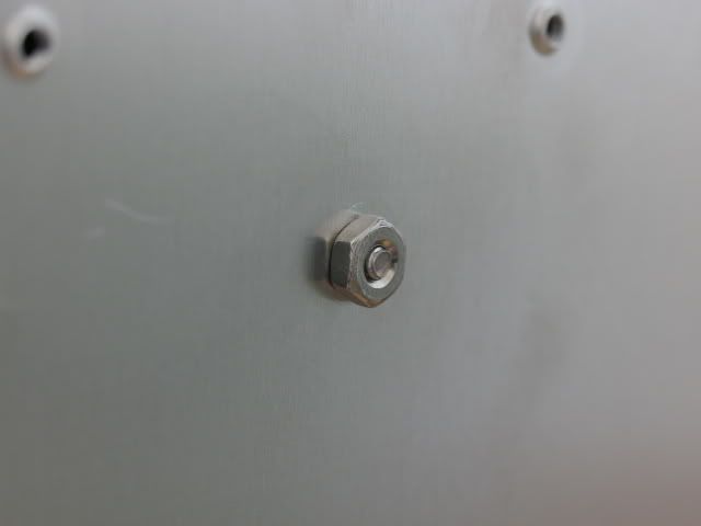
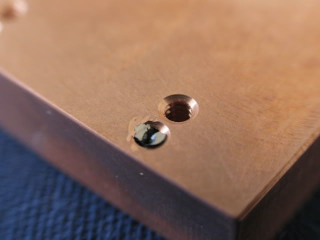
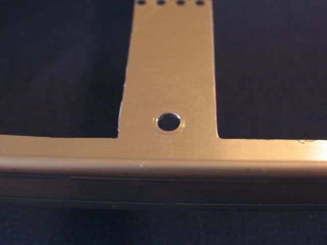
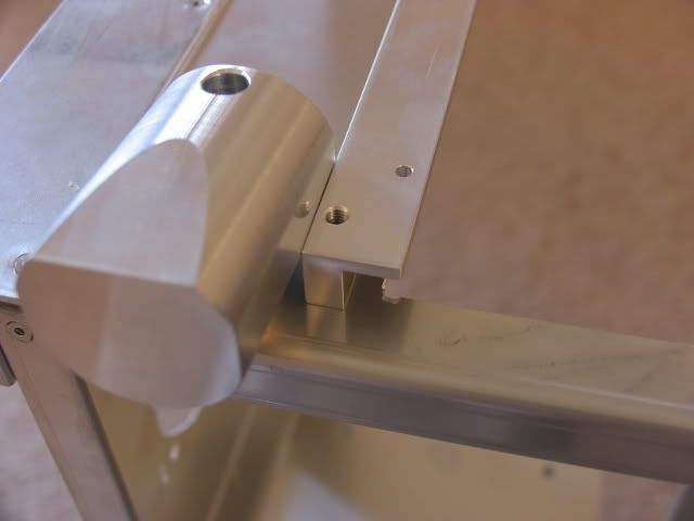
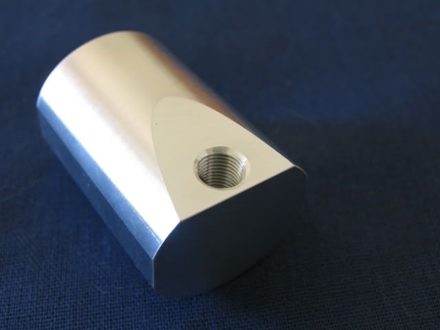
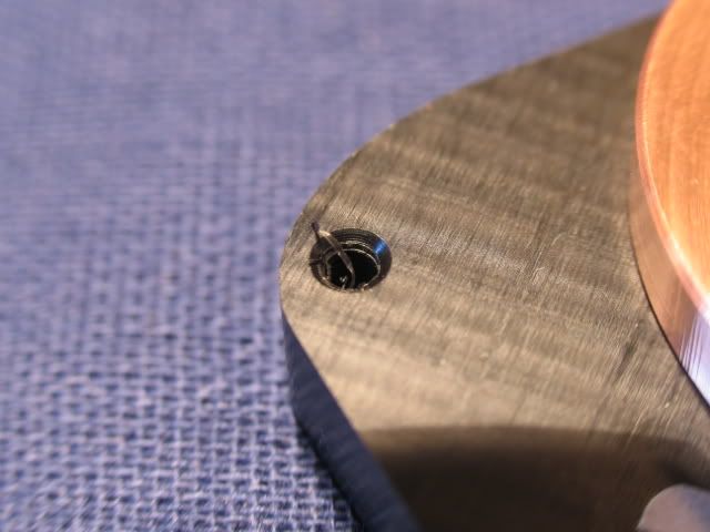
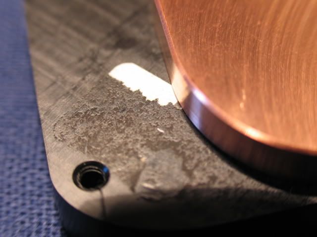
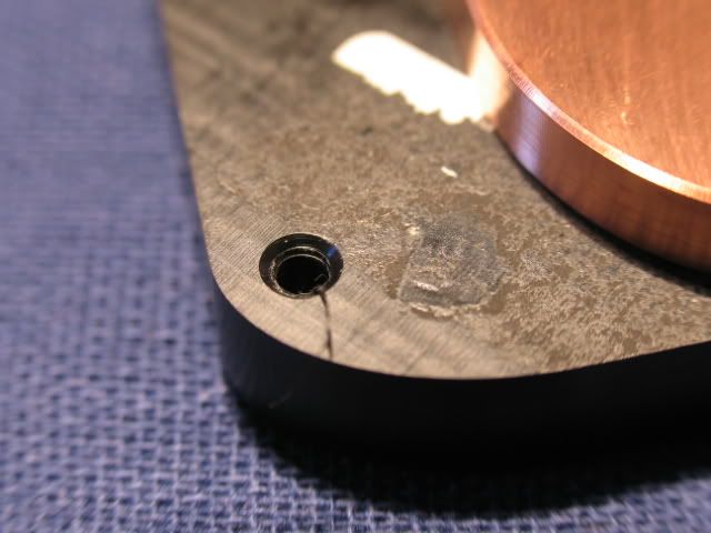
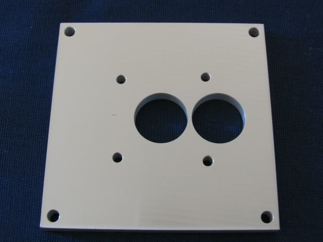
Here is the mounting hole (the thread is in the elbow). If you want to see how these were made, check my Beast III worklog
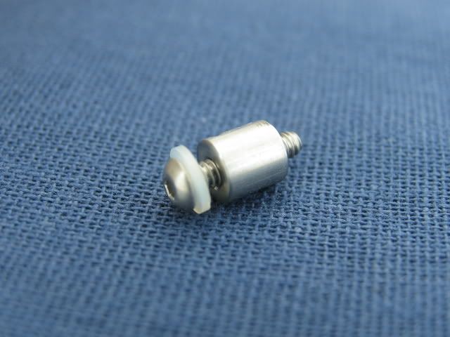
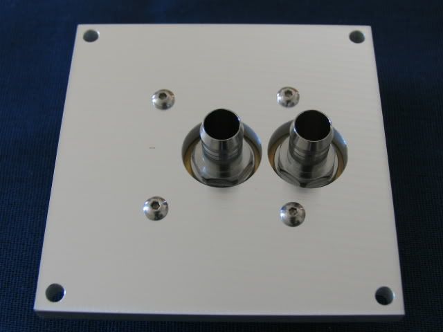
Rail with hole to show line-up
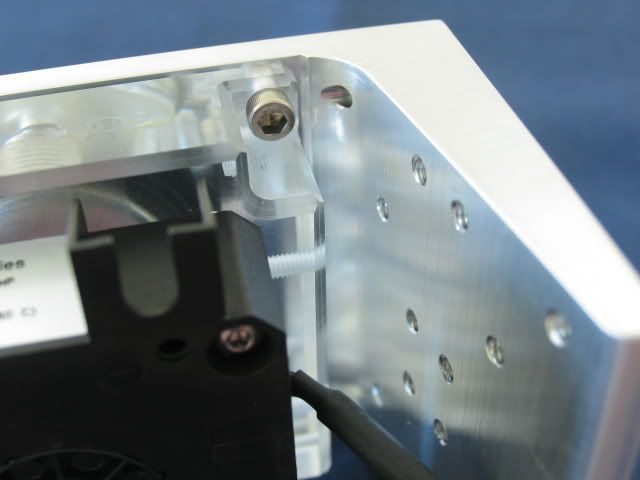
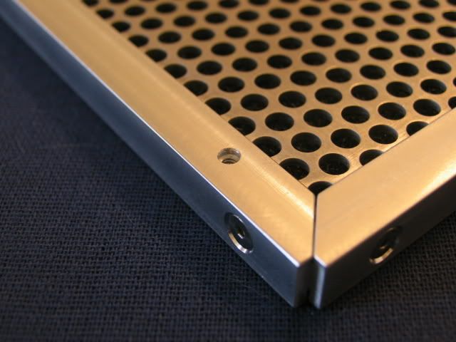
Attached
Here is the back end rail installed
Middle rail
Front end rail
The filters slide into position. I had intended to use four screws to hold each filter in place, but getting to all four screws once this thing is complete will be a PITA. I may only use two.
Since I want the filters to actually prevent dust from getting into the case, I had to block off all other entry points. Let’s start at the bottom. These are the holes under the PSU.
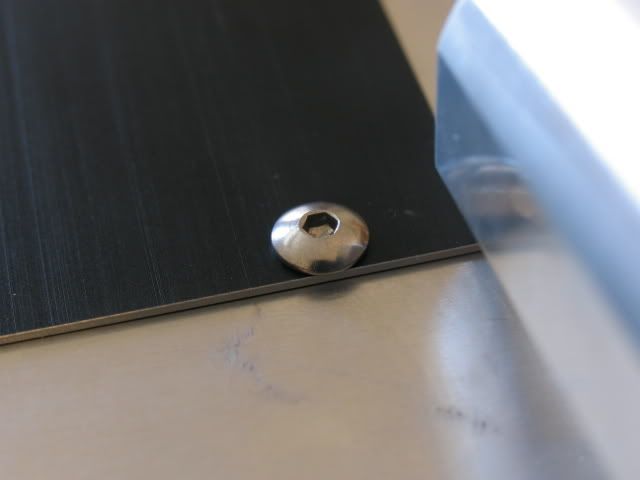
I squared up a piece of a remnant cut-out (actually the cutout for the top rad) to block these holes. The two holes in the center are for the PSU support.
Screws, washers and nuts
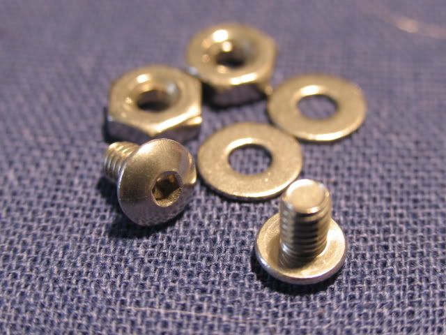
Installed
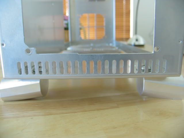
This is a shot of the slits below the PSU. I don’t have a remedy for this yet.
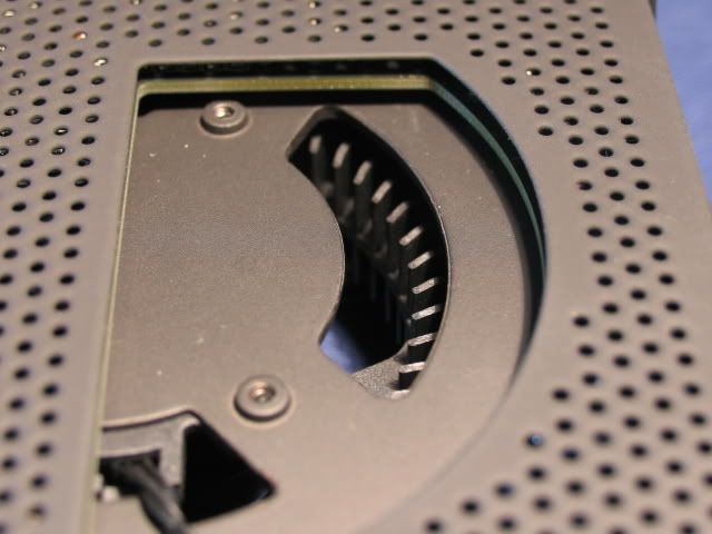
Next up are the holes for the GPU fan exhaust
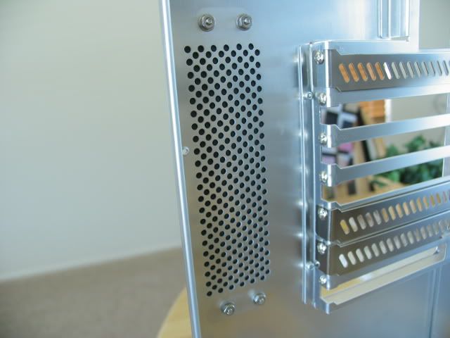
Covered
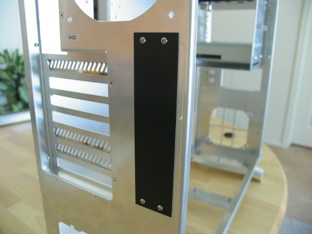
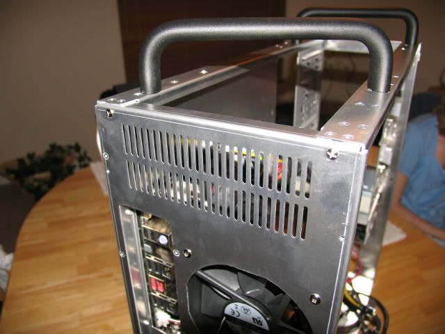
Next up are the top vents
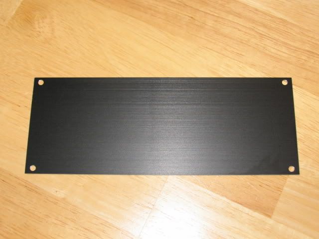
Plate
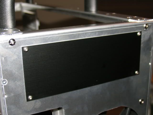
Installed
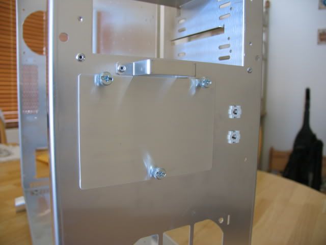
Here is the plate to cover the 3.5” drive bays.

Covered
Getting the 5.25” unused bays covered will be the hardest. I will probably use some clear silicone gel to cover any remaining air entry points. A complete seal is impossible, but I’ll certainly give it a shot.
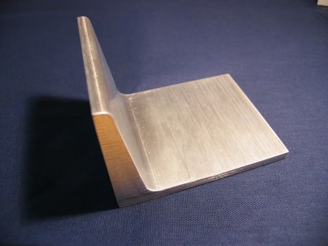
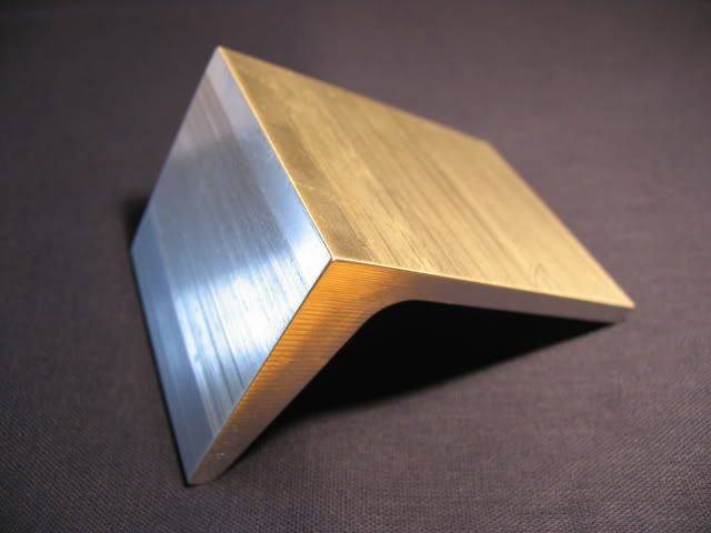
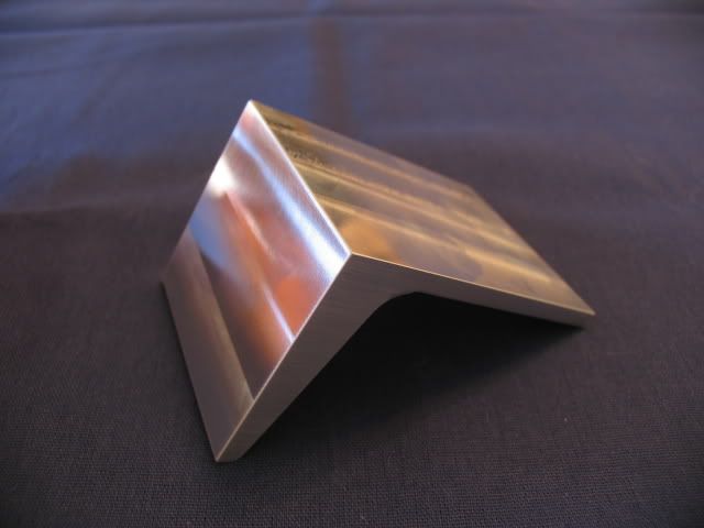
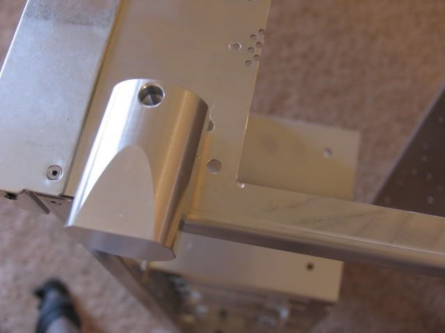
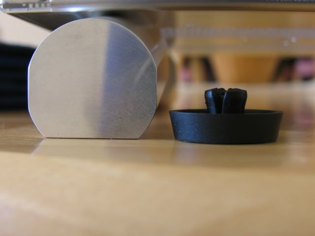
The stock rubber feet were not going to give me the proper height for the intake filters.
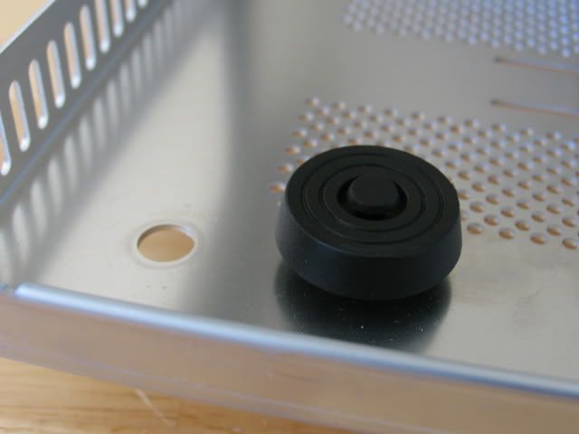
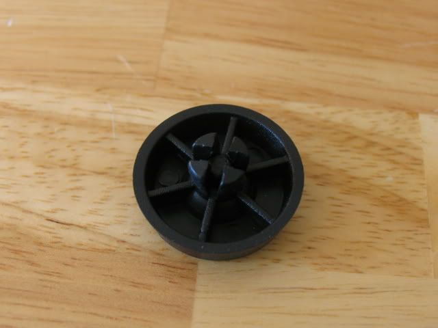
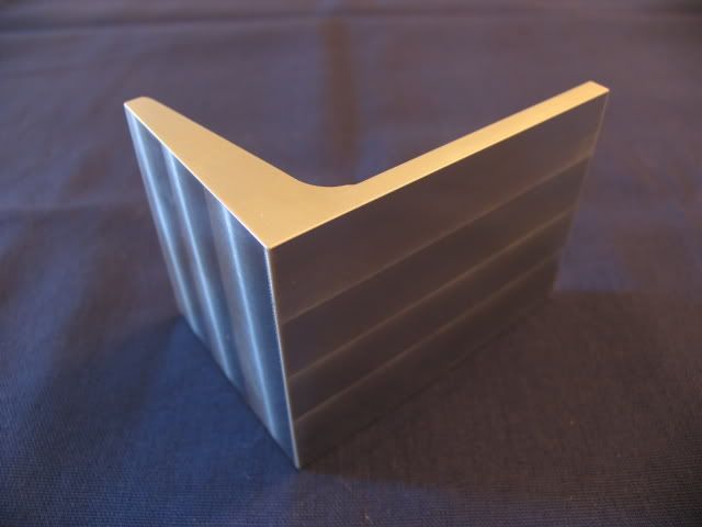
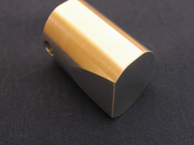
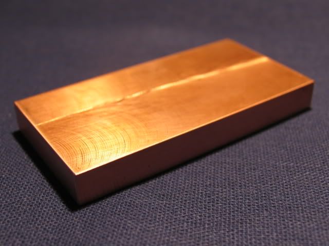
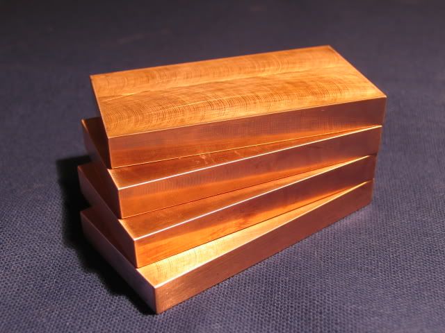
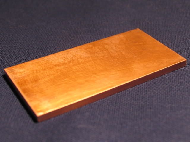
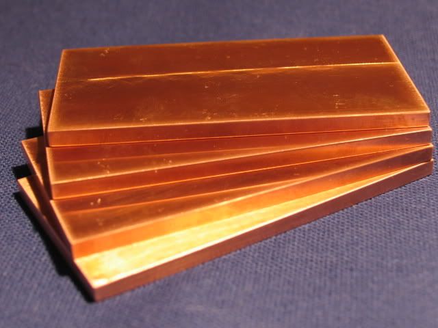
So I made these. They will also provide a wider stance to reduce side tippage
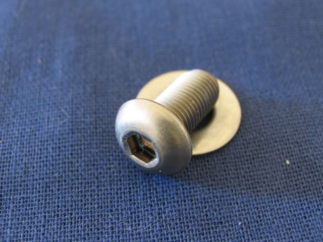
Screw and washer
Installed
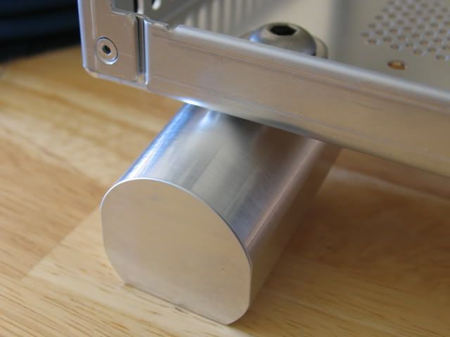
In this shot you can see the difference in height. More than enough for adequate air flow.
Here are some shots of the parts that will be utilized for this build. Plextor PS-850XA DVDRW
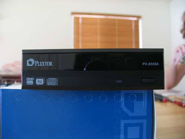
Shiny front.

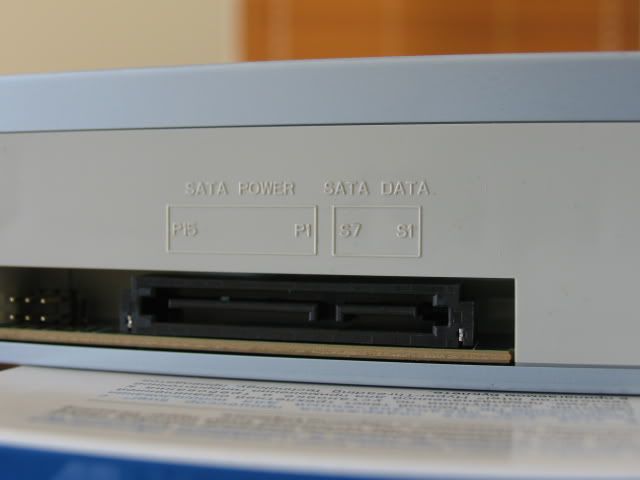
SATA interface
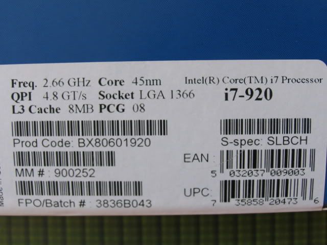
Next up is the CPU. ‘C’ stepping I believe
I was originally going to do a GTX 280 SLI set-up, but the water blocks (front and back) for two 280’s was going to run me almost $500.00. I am currently using an EVGA GTX 280 in my current system, and I purchased this BFG GTX 280 for the SLI
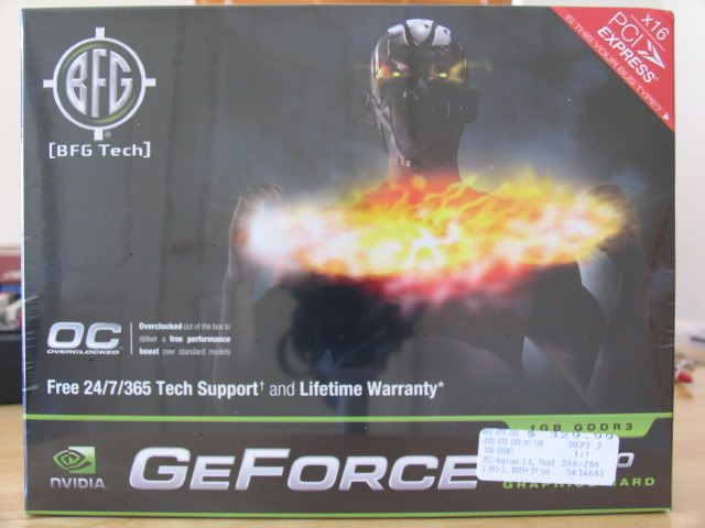
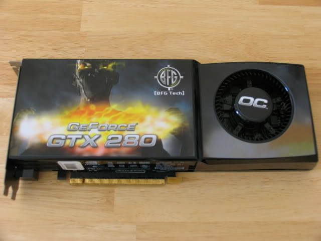
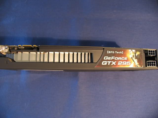
I know a pair of GTX 280’s in SLI is pretty decent and more than enough for a 24” monitor @ 1920 x 1200, but I couldn’t bring myself to drop the $$$ on the EK front and back blocks. So I decided to opt out and get a GTX 295. I know, I know, I can hear the groans now, but it is far easier to cool one card than two (tubing and set-up wise). To off-set the price, I’m planning on selling the 280’s.
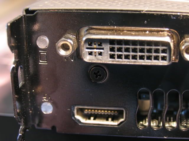
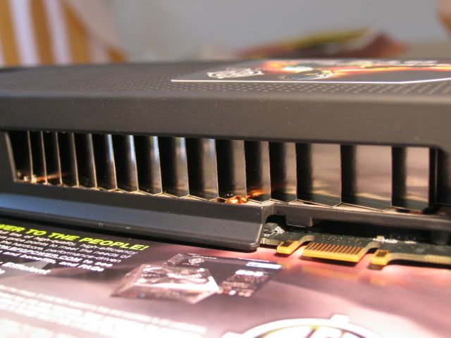
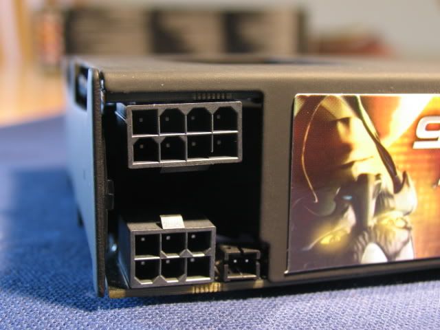
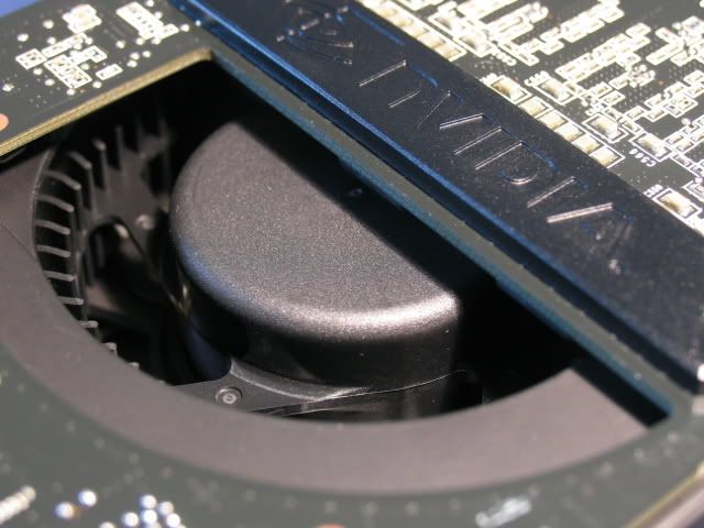
Here is the GTX 295 I picked up @ Fry’s (check that price!)
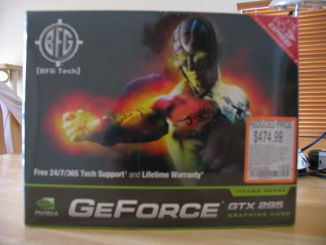
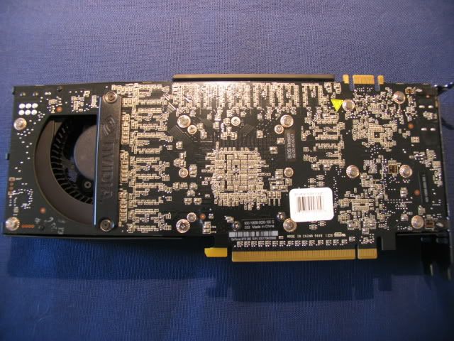
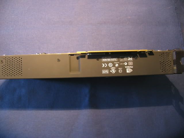
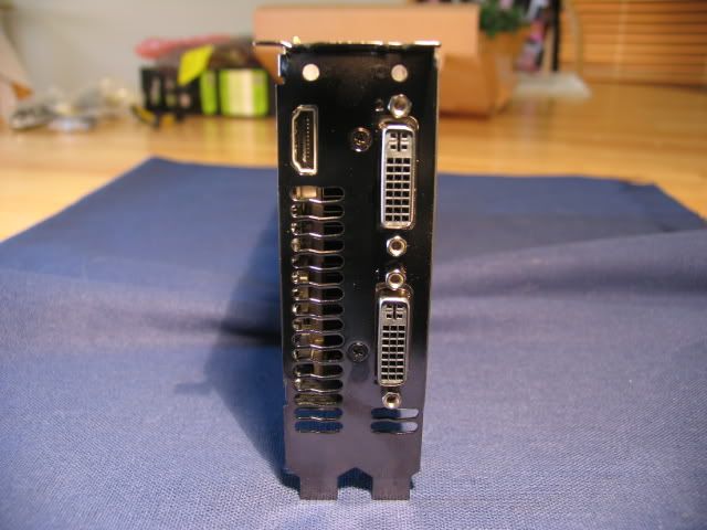
Candid shots (the covering on this card has the coolest rubber feel)
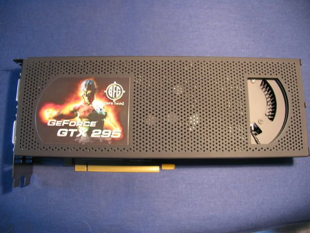
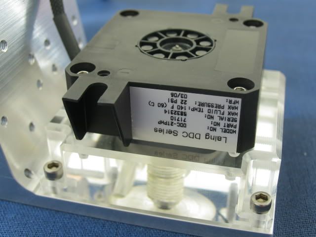
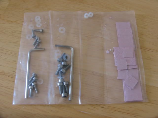
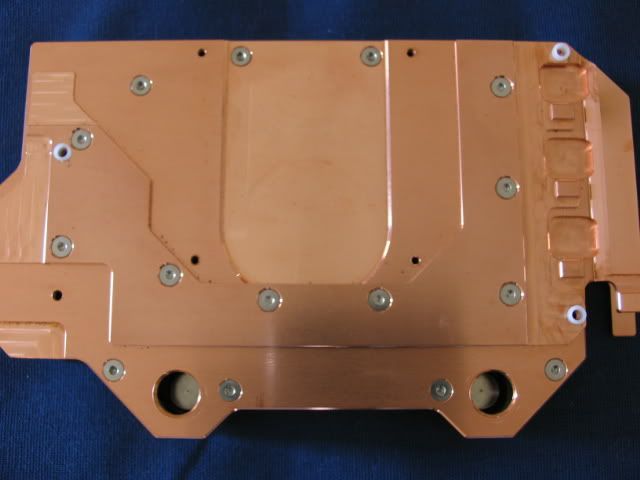
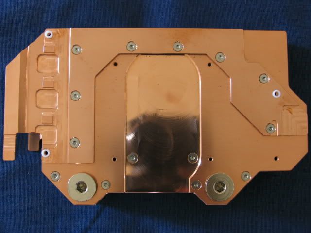
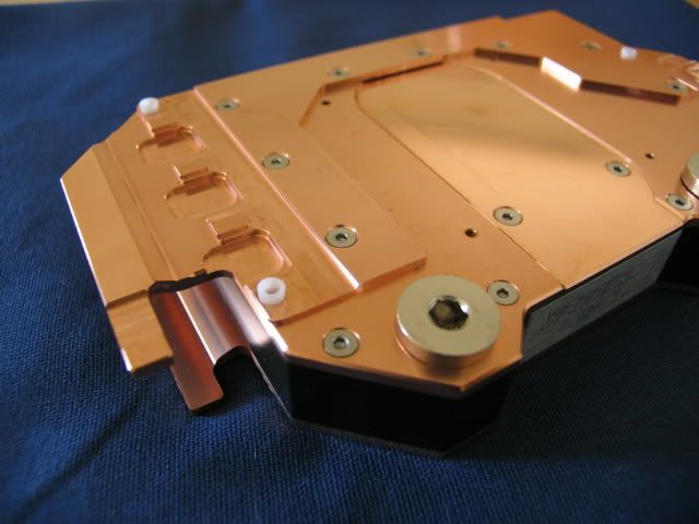
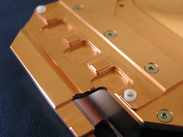
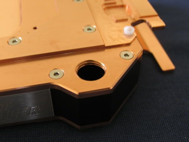
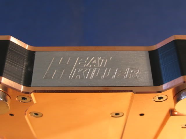
And to cool this beast I purchased the HeatKiller


Install goodies
I’m breaking in the 295 in my current system. I’ll have a post of the marriage of the 295 and the Heatkiller later.
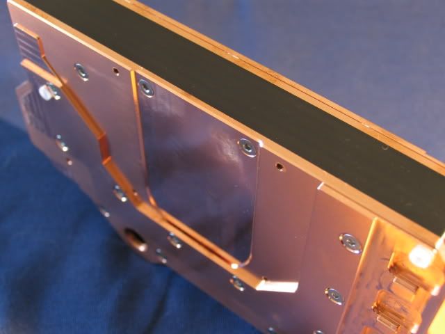
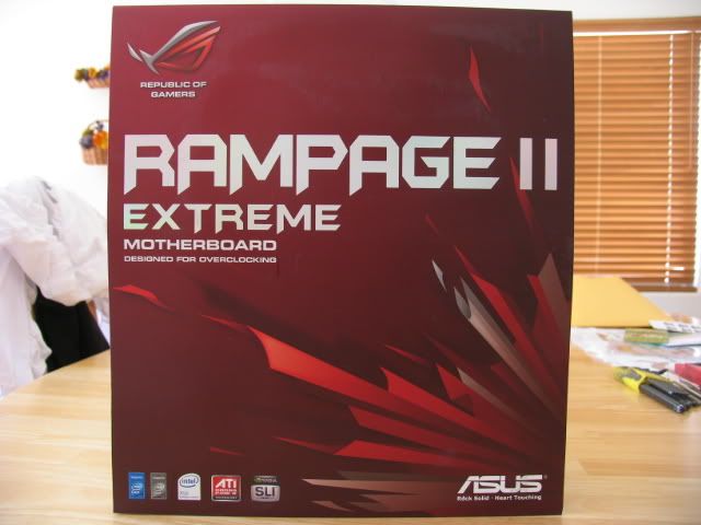
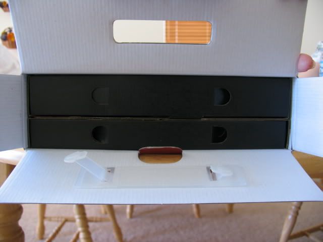
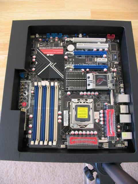
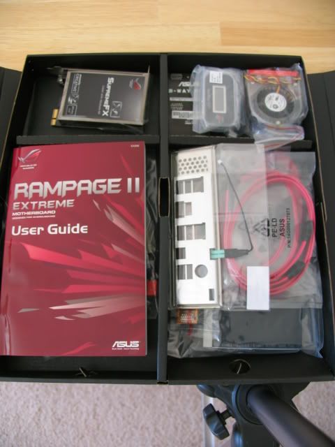
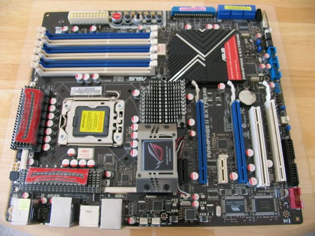
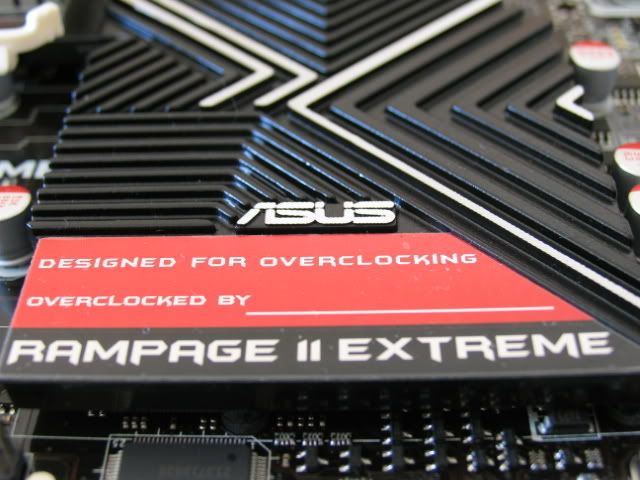
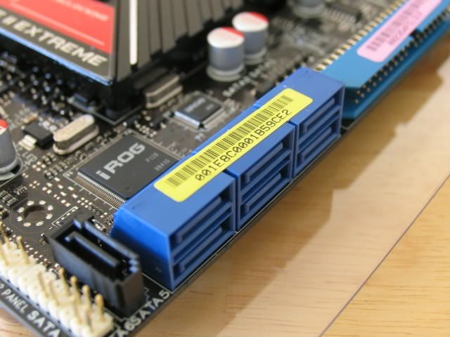
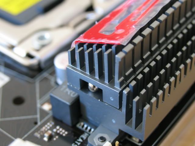
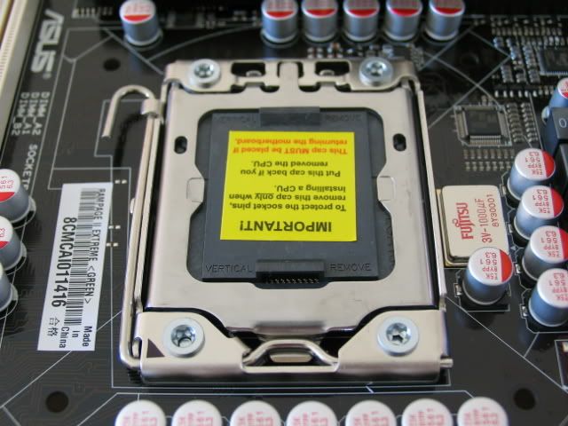
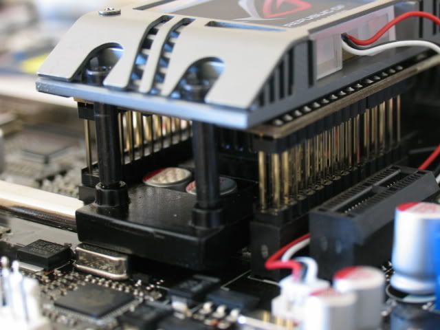
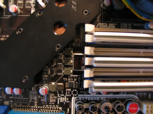
Here is the MOBO. Pics speak for themselves
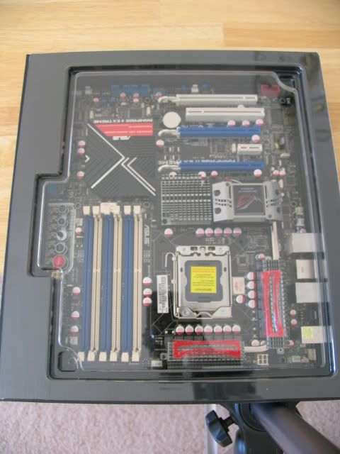
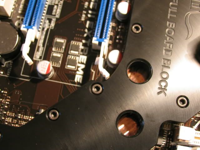
This shot gives you a good idea how much wider this board is (most boards end at the hole near the memory slot)
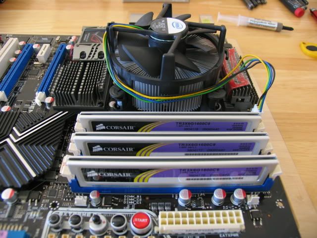
For initial testing I installed the CPU and memory
Here are the water cooling blocks for the mobo.
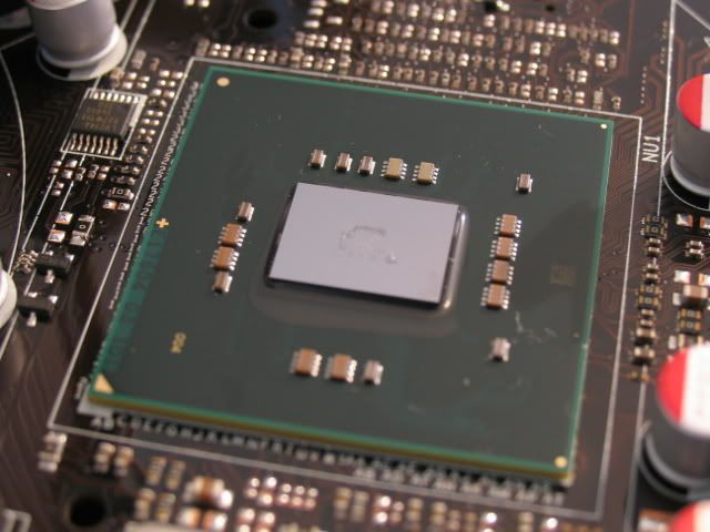
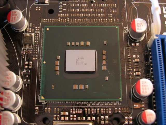
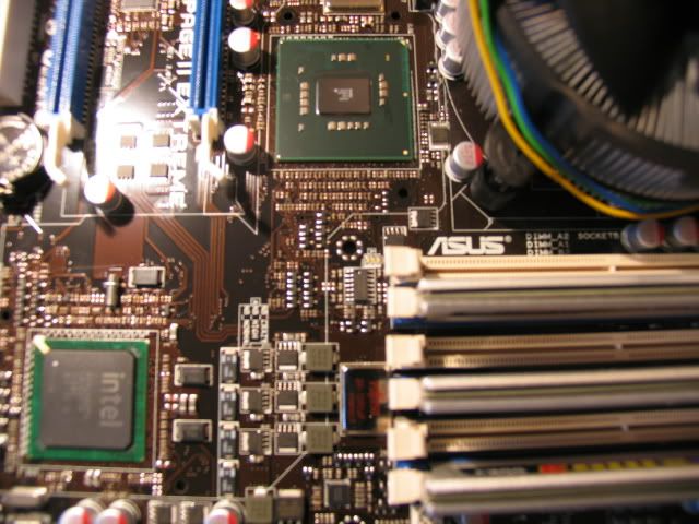
First, the naked nb
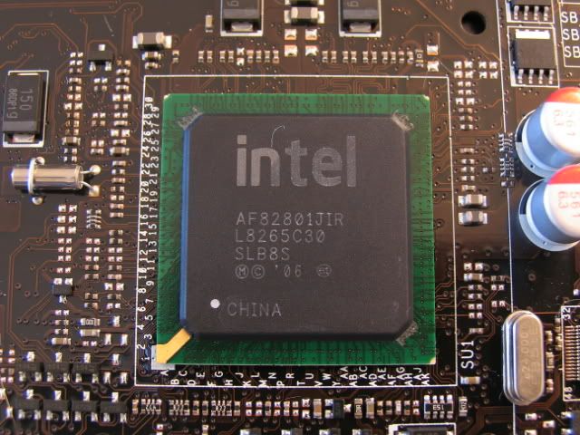
And sb
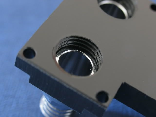
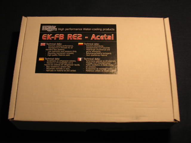
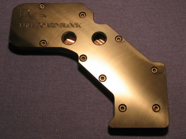
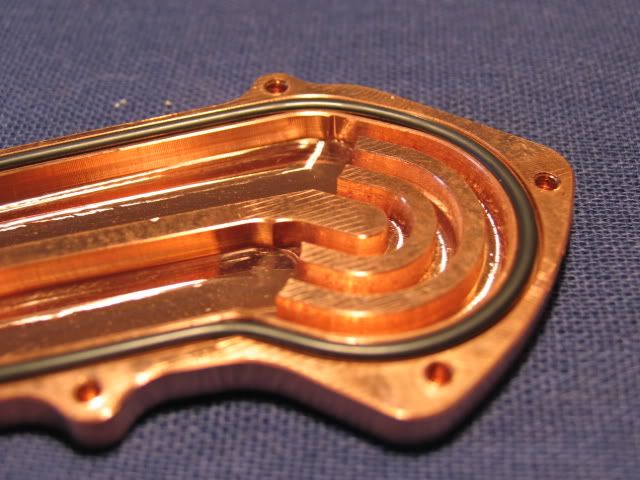
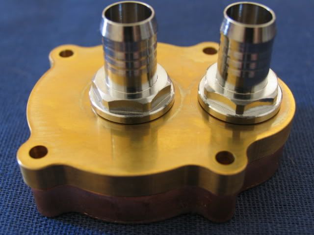
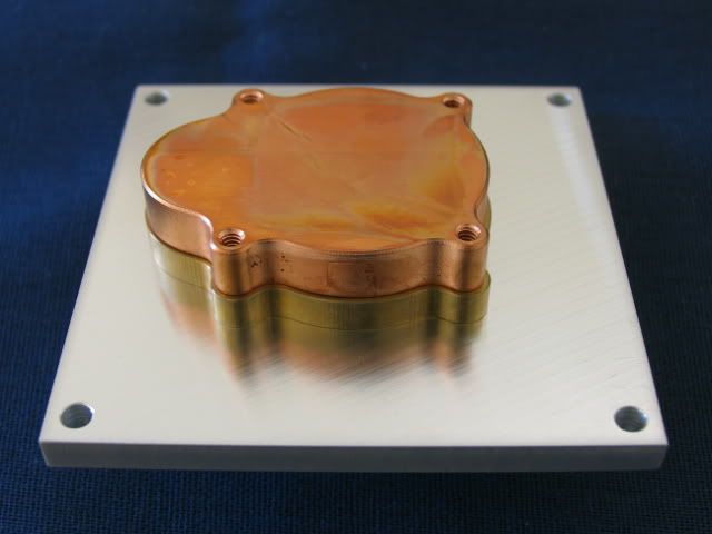
Next, the EK north and south bridge block with the acetal top
Looks like a quality control issue
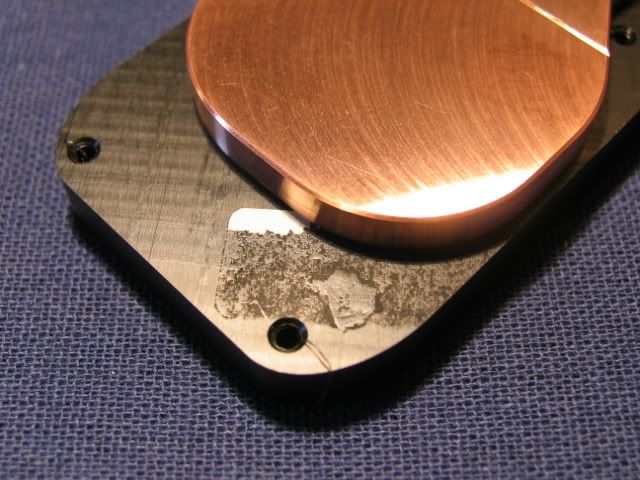
Look at those burrs!
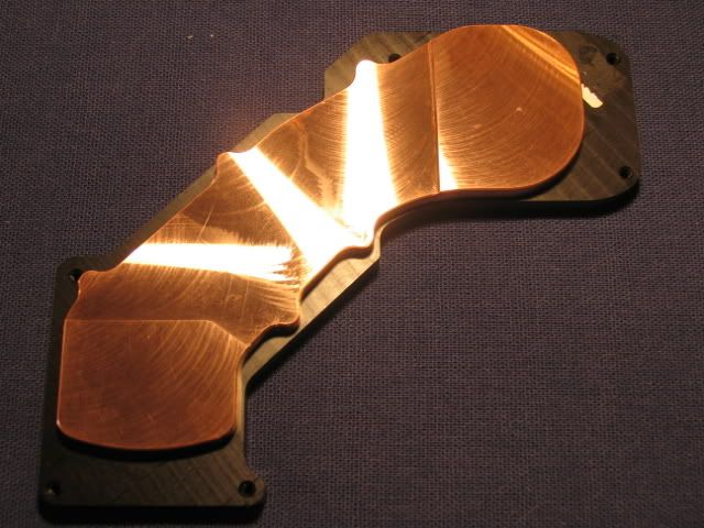
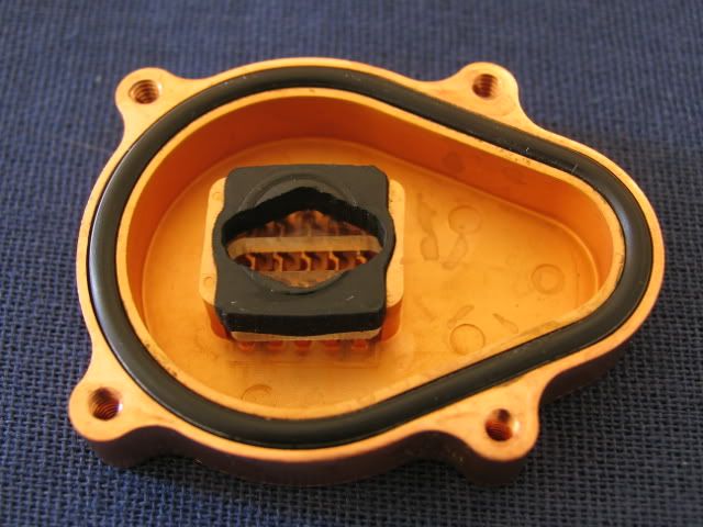
Inside
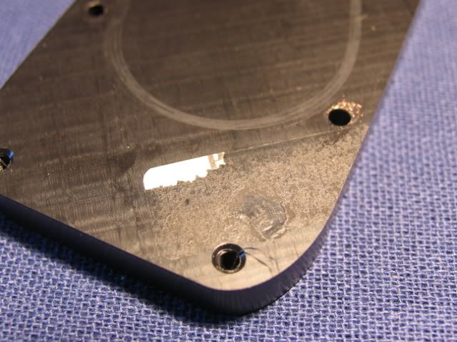
I was able to get the paper off, but what appears to be adhesive won’t come off. It seems like it will seal though.
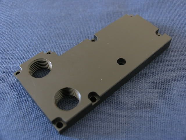
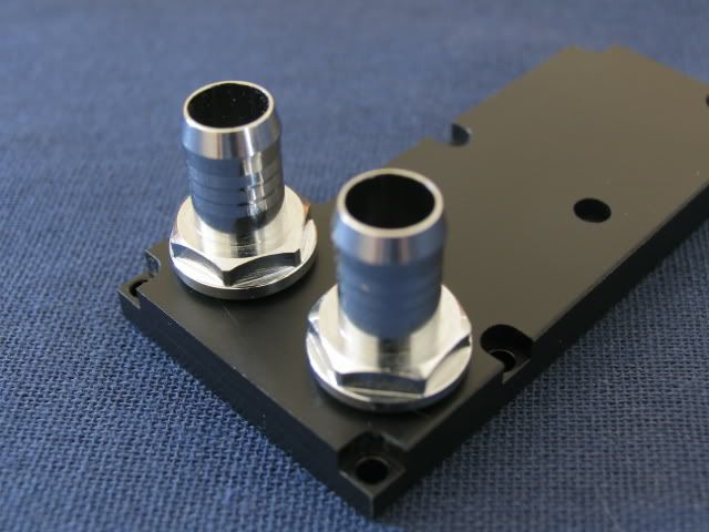
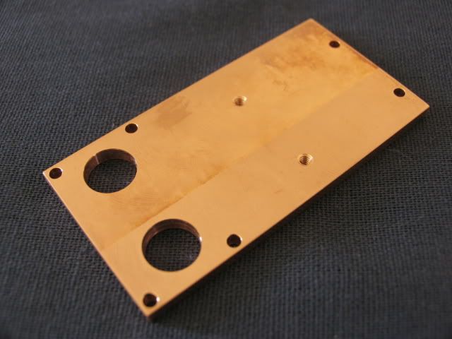
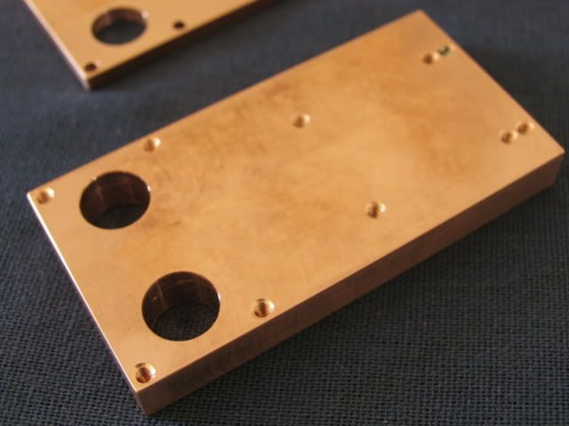
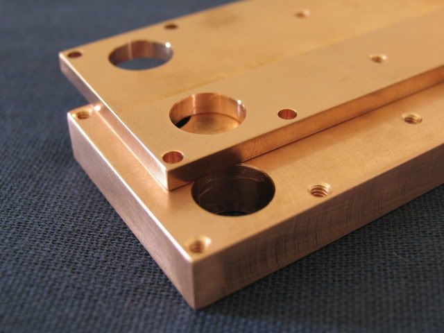
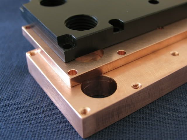
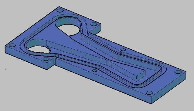
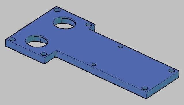
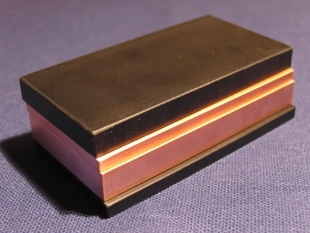
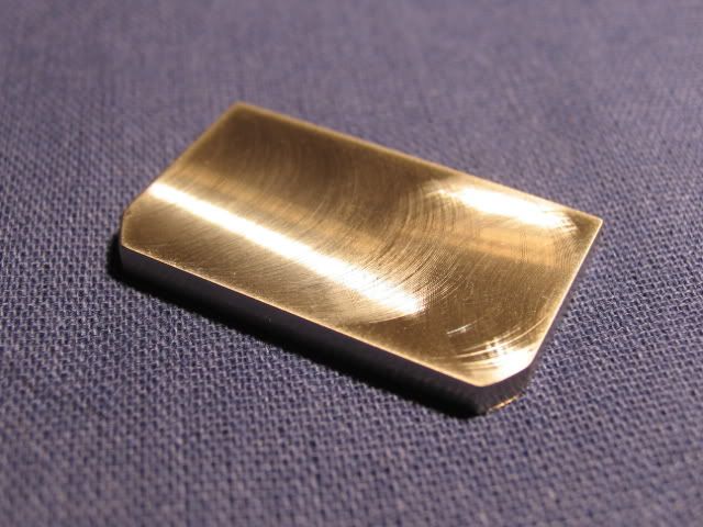
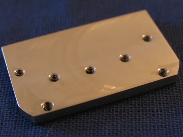
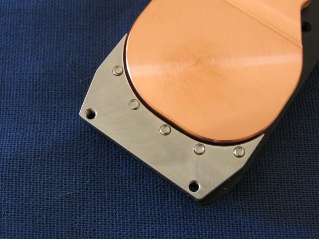
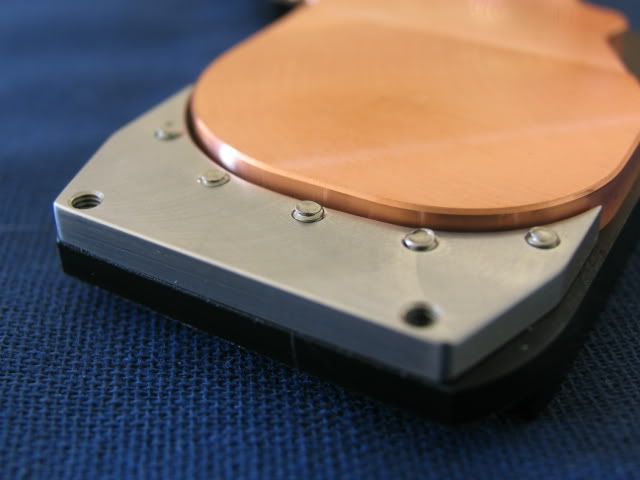
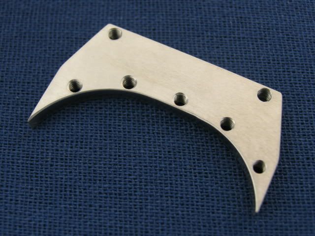
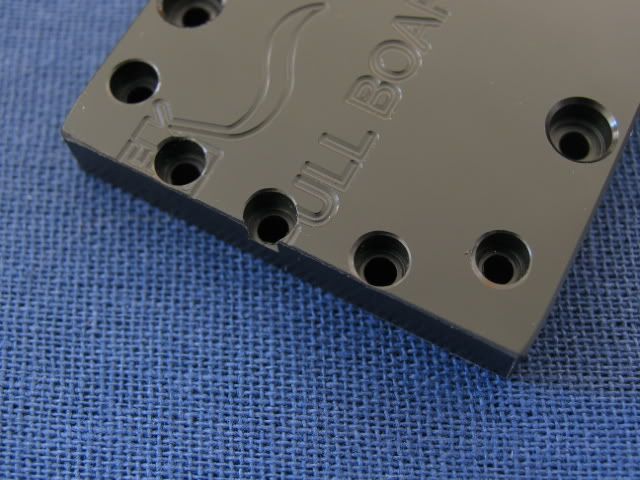
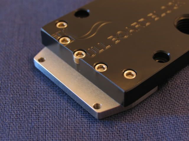
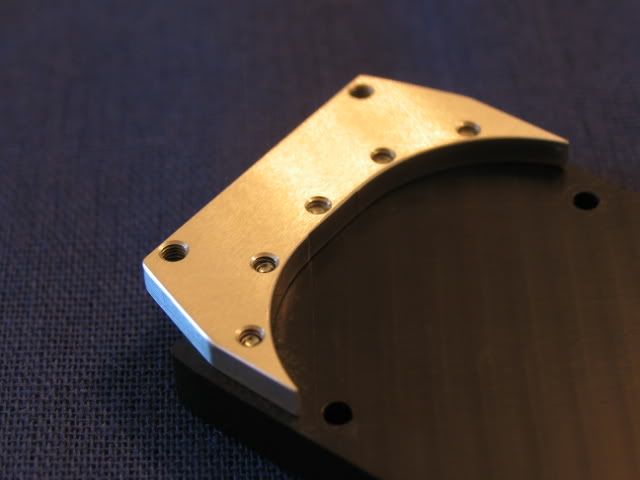
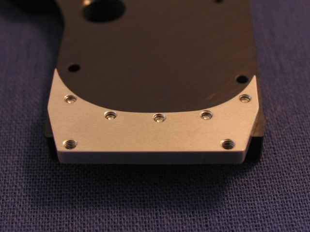
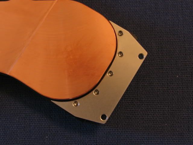
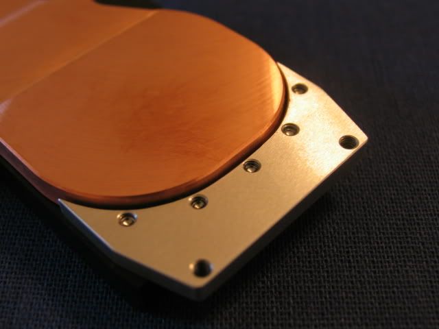
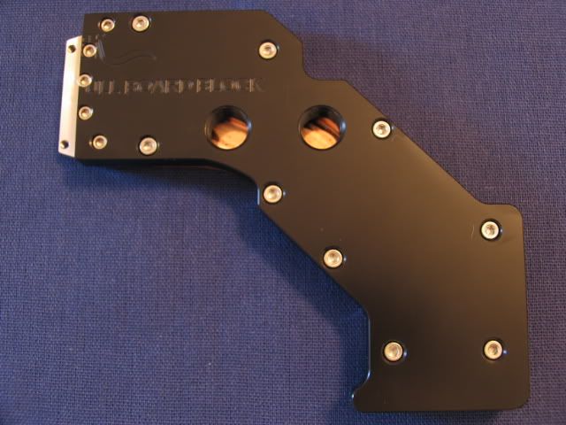
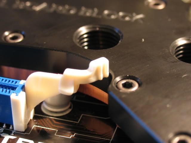
Next up is the block for the CPU. This is the same block I used for Beast 2.5, but the aluminum plate had to be remade to fit the different sizing for the mobo holes.
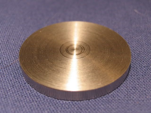
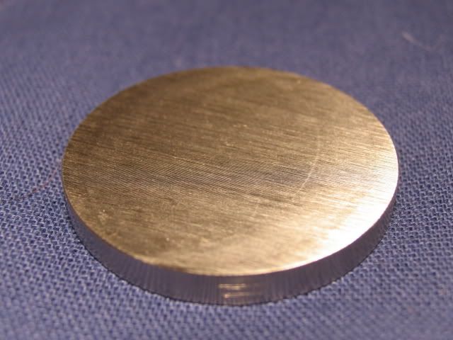
New top plate
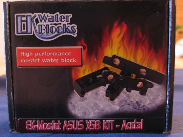
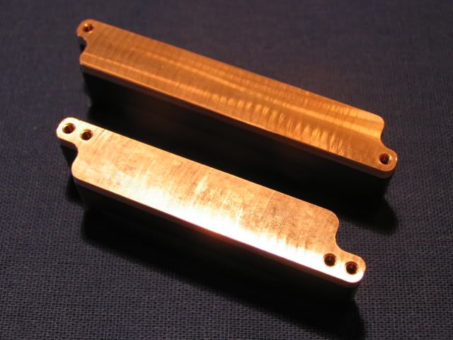
Next up are the mosfet blocks.
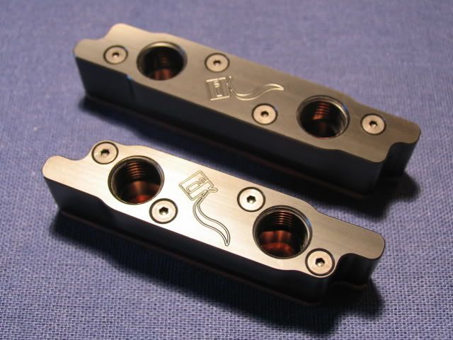
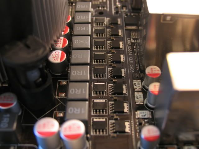
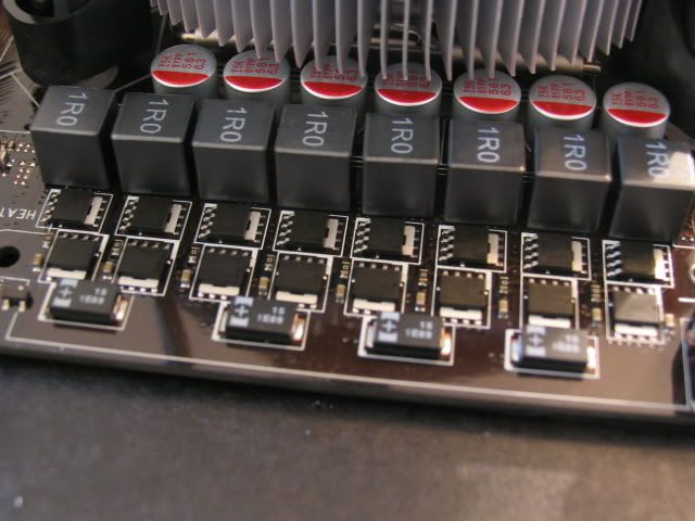
Naked mosfets
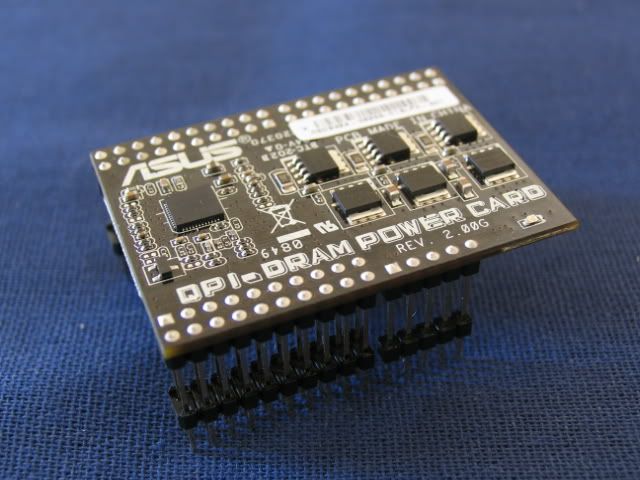
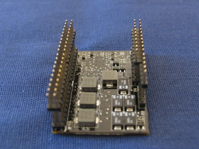
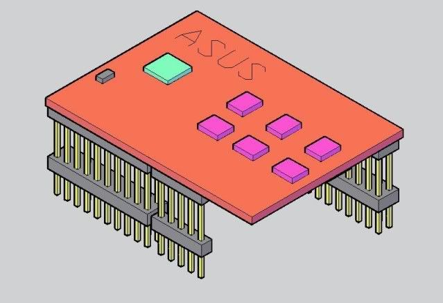
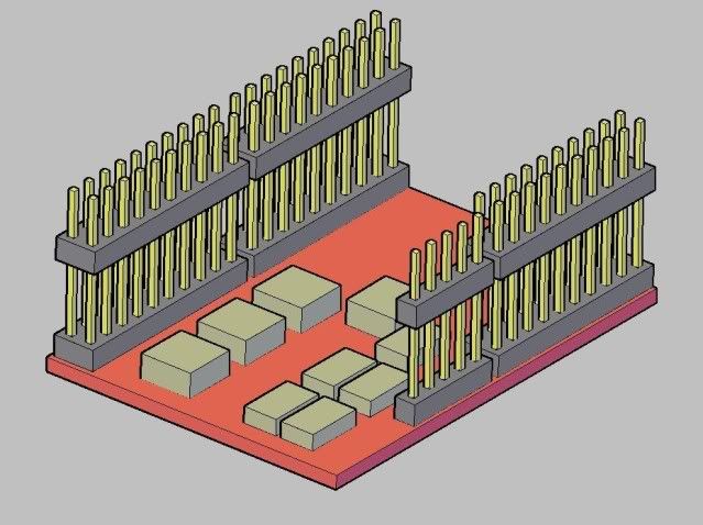
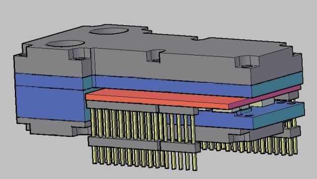
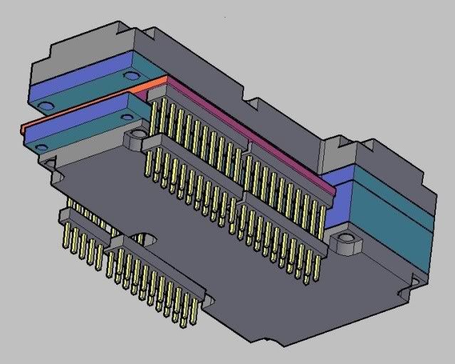
In order to get the stock heatpipes and blocks off the mobo, you are required to remove the QPI power riser card
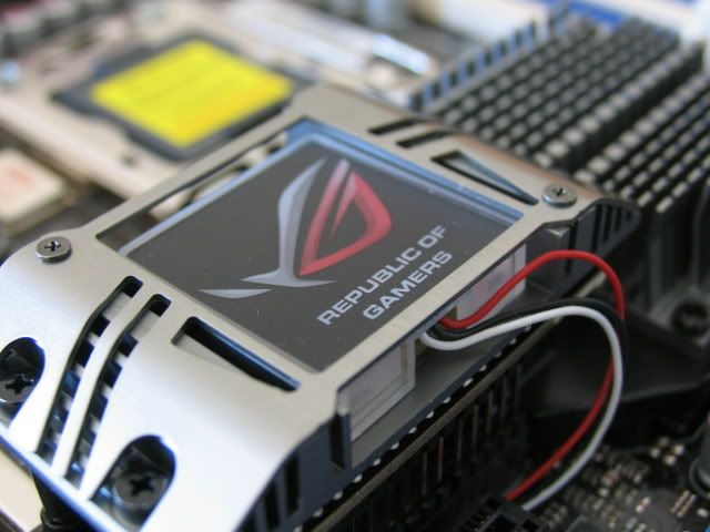
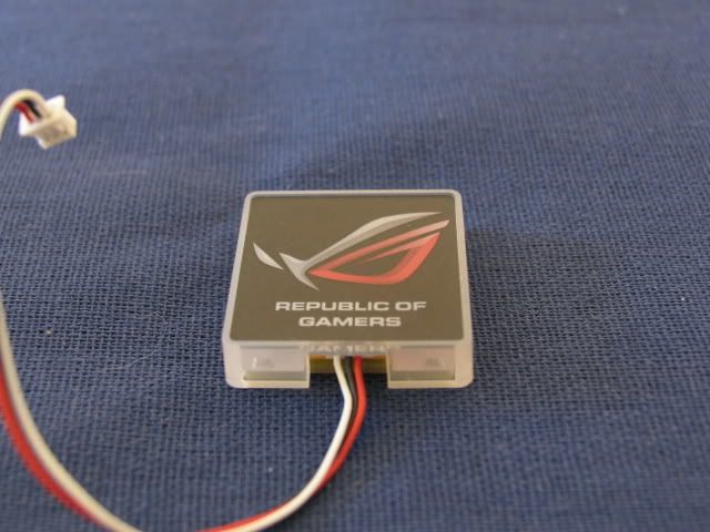
The ‘Republic of Gamers’ lighted logo
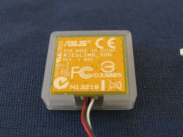
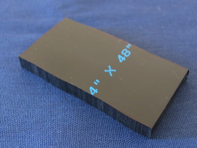
Backside
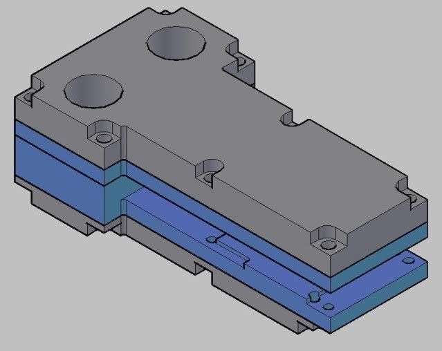
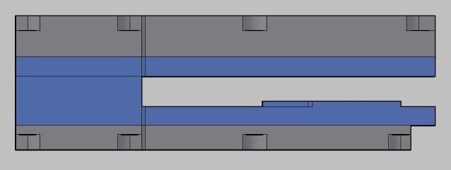
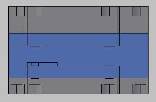
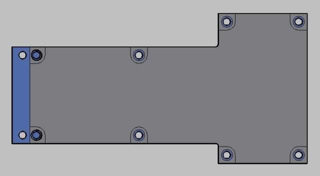
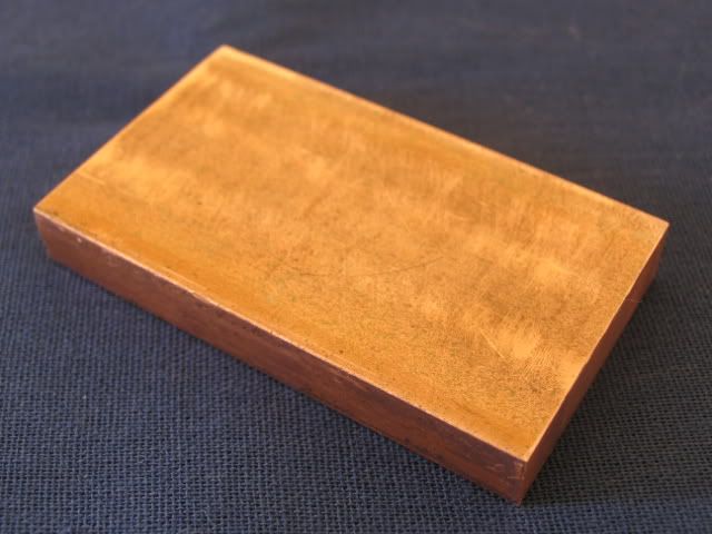
I wanted to reuse this logo, but I had no place to put it. There is a heatsink attached to the top of the QPI card, and this lighted logo is glued to it. But when you remove the stock heatpipes and blocks, there is nothing to attach the QPI card heatsink to. So I came up with a brilliant plan to make a water cooling block for it.
See next post.
Don’t fret, Beast III isn’t dead. I’ll actually be using some of it for this build. This build will be an update to Beast 2.75; the system I’m currently using.
Since Intel released its current speed champ, the i7 series, I knew it was time to upgrade. I had done some research and concluded the 920 proc was the way to go. An X58 mobo was also in order. And to get the best memory performance, 3 x 2GB of 1600 mem (minimum) was also on the menu.
I had a spare Lian-Li / Rocketfish case lying around, so I decided to use it as the backbone. I wanted to water cool as well. I will be using many of the parts from Beast 2.75 for most of the water cooling.
This case is certainly not as well built as some of my other Lian-Li’s, but it does have some features I like. The space at the top above the MOBO section is perfect for a triple rad set-up that is actually located inside the case (unlike Beast 2.75). I can also remove all the HDD cages since I’m planning on using an SSD for the OS and progs. I can also ditch the 3.5” cage since floppies are so out. First, some shots of the case.
First step was to add some handles (these are the same ones on the doors of the CNC lathes I use at work). These suckers are beefy, and at $20.00 each, they had better be.
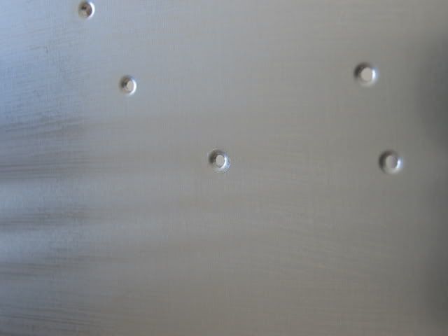
Here is a shot of the holes for the handles
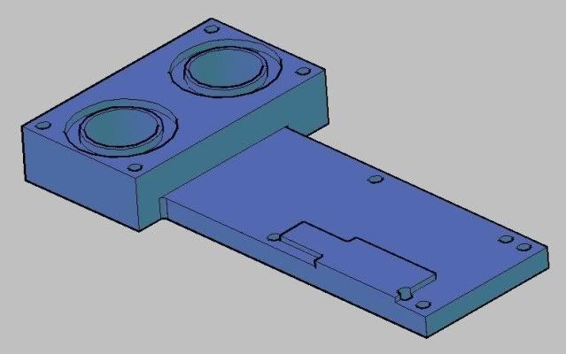
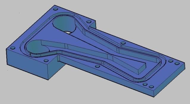
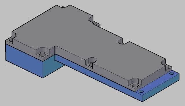
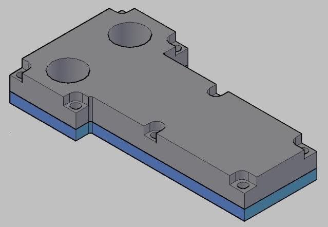
Here are the filters I made for Beast III. Since this case has the space at the bottom, I chose to incorporate them into this build. I also wanted to cut down on the dust intake as much as possible.
Here are the cut-outs for the air flow. I used my Roto-Zip to rough these out.
Wicked burrs!
I then filed the edges smooth. Back intake.
Front intake
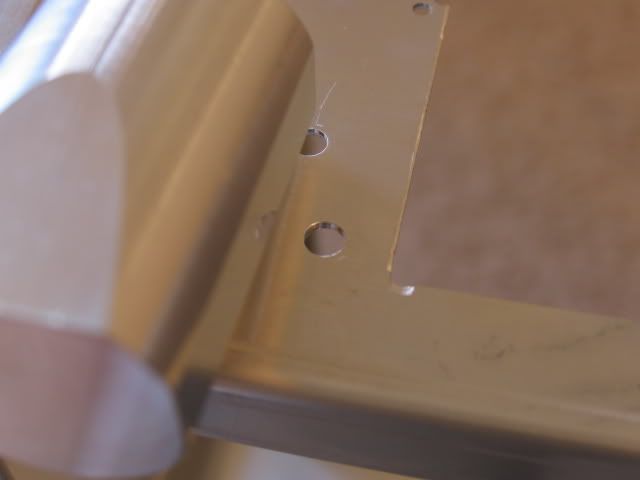
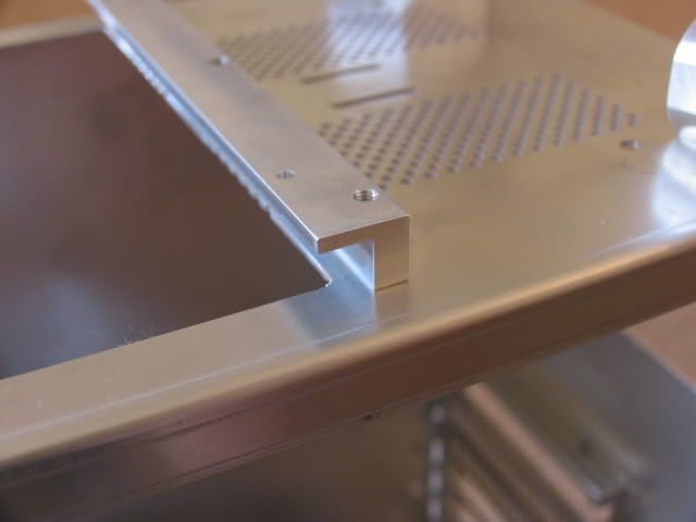
Holes for the rails to hold the filters
Close fit
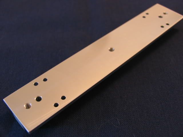
Here is the middle rail. There are two sets of holes because some idiot dimensioned in ‘Paper Space’ instead of ‘Model Space’. If you don’t know the difference, ask someone who uses Auto CAD. Shame on me.
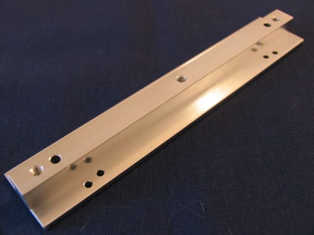
Here are the end rails
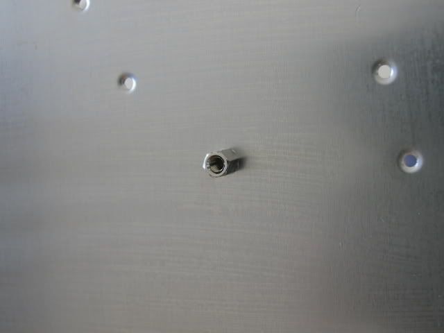
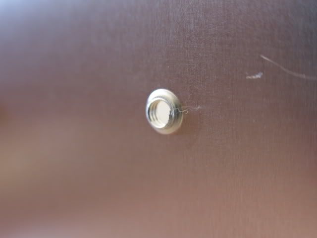
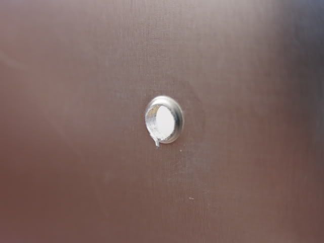
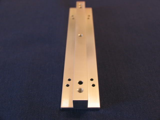
Here is the mounting hole (the thread is in the elbow). If you want to see how these were made, check my Beast III worklog
Rail with hole to show line-up
Attached
Here is the back end rail installed
Middle rail
Front end rail
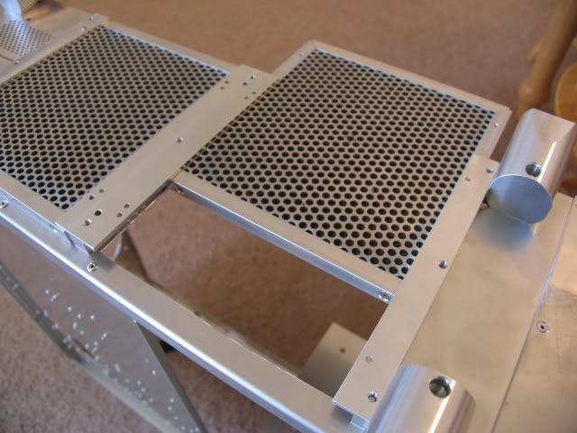
The filters slide into position. I had intended to use four screws to hold each filter in place, but getting to all four screws once this thing is complete will be a PITA. I may only use two.
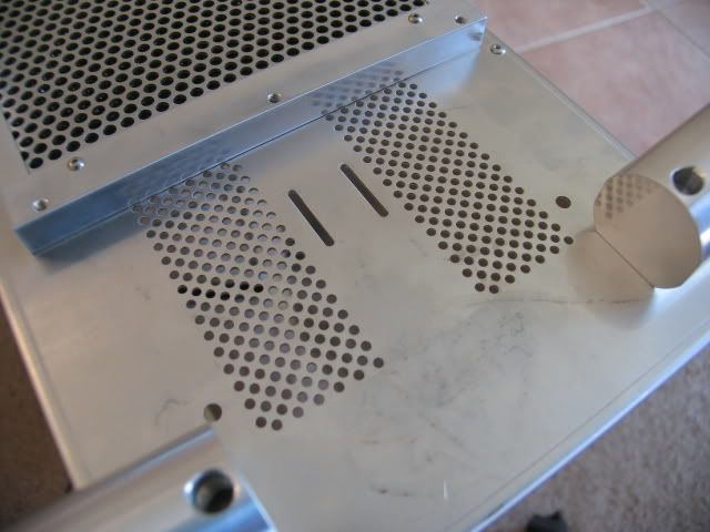
Since I want the filters to actually prevent dust from getting into the case, I had to block off all other entry points. Let’s start at the bottom. These are the holes under the PSU.
I squared up a piece of a remnant cut-out (actually the cutout for the top rad) to block these holes. The two holes in the center are for the PSU support.
Screws, washers and nuts
Installed
This is a shot of the slits below the PSU. I don’t have a remedy for this yet.
Next up are the holes for the GPU fan exhaust
Covered
Next up are the top vents
Plate
Installed
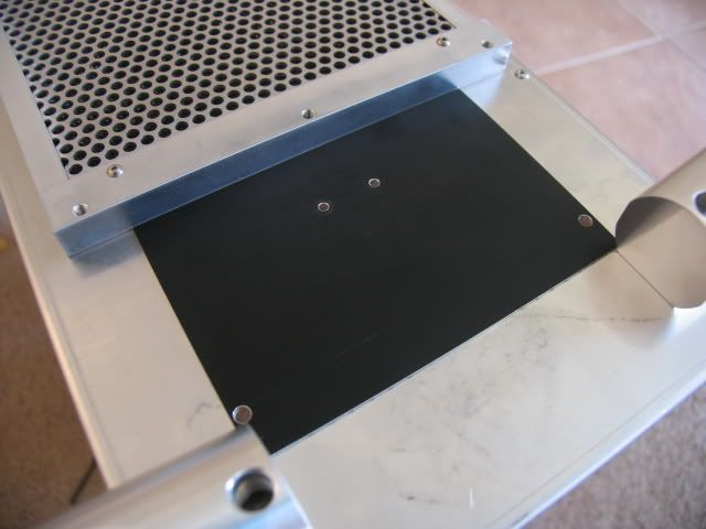
Here is the plate to cover the 3.5” drive bays.
Covered
Getting the 5.25” unused bays covered will be the hardest. I will probably use some clear silicone gel to cover any remaining air entry points. A complete seal is impossible, but I’ll certainly give it a shot.
The stock rubber feet were not going to give me the proper height for the intake filters.
So I made these. They will also provide a wider stance to reduce side tippage
Screw and washer
Installed
In this shot you can see the difference in height. More than enough for adequate air flow.
Here are some shots of the parts that will be utilized for this build. Plextor PS-850XA DVDRW
Shiny front.
SATA interface
Next up is the CPU. ‘C’ stepping I believe
I was originally going to do a GTX 280 SLI set-up, but the water blocks (front and back) for two 280’s was going to run me almost $500.00. I am currently using an EVGA GTX 280 in my current system, and I purchased this BFG GTX 280 for the SLI
I know a pair of GTX 280’s in SLI is pretty decent and more than enough for a 24” monitor @ 1920 x 1200, but I couldn’t bring myself to drop the $$$ on the EK front and back blocks. So I decided to opt out and get a GTX 295. I know, I know, I can hear the groans now, but it is far easier to cool one card than two (tubing and set-up wise). To off-set the price, I’m planning on selling the 280’s.
Here is the GTX 295 I picked up @ Fry’s (check that price!)
Candid shots (the covering on this card has the coolest rubber feel)
And to cool this beast I purchased the HeatKiller
Install goodies
I’m breaking in the 295 in my current system. I’ll have a post of the marriage of the 295 and the Heatkiller later.
Here is the MOBO. Pics speak for themselves
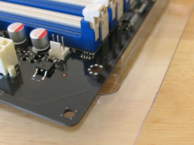
This shot gives you a good idea how much wider this board is (most boards end at the hole near the memory slot)
For initial testing I installed the CPU and memory
Here are the water cooling blocks for the mobo.
First, the naked nb
And sb
Next, the EK north and south bridge block with the acetal top
Looks like a quality control issue
Look at those burrs!
Inside
I was able to get the paper off, but what appears to be adhesive won’t come off. It seems like it will seal though.
Next up is the block for the CPU. This is the same block I used for Beast 2.5, but the aluminum plate had to be remade to fit the different sizing for the mobo holes.
New top plate
Next up are the mosfet blocks.
Naked mosfets
In order to get the stock heatpipes and blocks off the mobo, you are required to remove the QPI power riser card
The ‘Republic of Gamers’ lighted logo
Backside
I wanted to reuse this logo, but I had no place to put it. There is a heatsink attached to the top of the QPI card, and this lighted logo is glued to it. But when you remove the stock heatpipes and blocks, there is nothing to attach the QPI card heatsink to. So I came up with a brilliant plan to make a water cooling block for it.
See next post.
Last edited:


")