Navigation
Install the app
How to install the app on iOS
Follow along with the video below to see how to install our site as a web app on your home screen.
Note: This feature may not be available in some browsers.
More options
You are using an out of date browser. It may not display this or other websites correctly.
You should upgrade or use an alternative browser.
You should upgrade or use an alternative browser.
New Samsung 4k for everyone.
- Thread starter seanclayton
- Start date

Lateralus
More [H]uman than Human
- Joined
- Aug 7, 2004
- Messages
- 18,538
Does the input matter (i.e. does it have to be HDMI 2 for DVI/PC)? If so, maybe he's using HDMI 1 and that's why he's not getting 4:4:4.
Last night I noticed my 50" "shrinking" - it's not overly big, but also not small. The 40" seemed small after a day. I think the 48-50" size is perfect. My desk is 30" deep, using multiple pieces of http://www.ikea.com/us/en/catalog/products/50106773/ and http://www.ikea.com/us/en/catalog/products/90106771/ .
I'd say 24-30" viewing distance works for desktop usage with the 40", 30-40" works with the 48/50". 36" distance with the 50" screen is close to perfect - fully usable without needing to move your head, but enough to fill most of your center gaze.
I'd say 24-30" viewing distance works for desktop usage with the 40", 30-40" works with the 48/50". 36" distance with the 50" screen is close to perfect - fully usable without needing to move your head, but enough to fill most of your center gaze.
Does the input matter (i.e. does it have to be HDMI 2 for DVI/PC)? If so, maybe he's using HDMI 1 and that's why he's not getting 4:4:4.
6 series only work on HDMI 1.
WorldExclusive
[H]F Junkie
- Joined
- Apr 26, 2009
- Messages
- 11,548
Is game mode still 4:2;2 on the 1214 firmware? I'll update later tonight after work to see what's up.
It's still 4:2:2
Lateralus
More [H]uman than Human
- Joined
- Aug 7, 2004
- Messages
- 18,538
6 series only work on HDMI 1.
That's right. I was confusing him with TDSlam720 who got a 7100. Mah bad!
TheDarkTao
Gawd
- Joined
- Feb 5, 2005
- Messages
- 800
Thats soooo weird... I have totally lost 4:4:4 if set to DVI/PC. I believe ya cyph.
Damn annoying. Guess a bug? I REALLY get the feeling the input lag and blur seems ALOT better under this firmware. This is after quite a bit of gaming on d3, dota, starcraft and L4d2. I am very sensitive to it (as in aware) but not necessarily bothered over the top. But it seems alot nicer now.
I loved the display from the start... almost before I bought it ; ) But this last update seems great except for my bad luck with pc/dvi input.
I would love to see some pc mode lag numbers
Andrew_WOT
n00b
- Joined
- May 15, 2015
- Messages
- 30
So JS8500 does not have Game mode, i.e. high input lag?Yeah. I pretty much gave up trying to buy the js8500 since you can't toggle gamemode on any picture setting like the glorious Panasonic tvs. Cx800 here I cum.
The panel is so much better.
darkangelamd
Limp Gawd
- Joined
- Jul 26, 2004
- Messages
- 280
How can you tell if it is in 4:4:4?
Andrew_WOT
n00b
- Joined
- May 15, 2015
- Messages
- 30
seanclayton
Gawd
- Joined
- Oct 25, 2008
- Messages
- 882
It does, but it sucks. Picture quality looks too crappy, and without gamemode it lags too much.So JS8500 does not have Game mode, i.e. high input lag?
The panel is so much better.
Let's just say Panasonic CX800 >>> JS8500. Picture quality does not suffer with or without game mode. The colors are more accurate, and the gamut is much higher than Samsung's quantum dot---covering only up to 92% DCI p3.
Andrew_WOT
n00b
- Joined
- May 15, 2015
- Messages
- 30
It does, but it sucks. Picture quality looks too crappy, and without gamemode it lags too much.
Let's just say Panasonic CX800 >>> JS8500. Picture quality does not suffer with or without game mode. The colors are more accurate, and the gamut is much higher than Samsung's quantum dot---covering only up to 92% DCI p3.
I just was online with Samsung rep and she assured me that JS8500 does not have Game mode at all.
How is the input lag on CX800?
Seems like the smallest CX800 available in US is 55", a bit big for a desktop monitor.
darkangelamd
Limp Gawd
- Joined
- Jul 26, 2004
- Messages
- 280
Andrew_WOT
n00b
- Joined
- May 15, 2015
- Messages
- 30
But now I think she was clueless as JS8500 manual covers how to enable this mode.I just was online with Samsung rep and she assured me that JS8500 does not have Game mode at all.
Accidentally stumbled upon another way to solve the truncated and stacked windows problem. As long as you set the PC sleep time to less than the TV auto off time, then the PC will still detect the TV and retain the windows size and position when it goes to sleep.
black88mx6
n00b
- Joined
- Mar 4, 2012
- Messages
- 21
I have successfully setup my Pulse-Eight CEC adapter to turn on / off my Samsung UN40JU7500 either for sleep or system startup or shutdown under Windows 7. It may or may not work with other OS. LibCEC Trax(x64) runs as a Task Scheduled item at system start-up. All other media center items disabled.
Config from Nvidia 980 HDMI - 1ft HDMI to Pulse-Eight CEC - 1ft HDMI - Samsung Mini Box
Still able to run 4K 60 Hertz at 444
Now this large TV is working like a regular monitor.")
Config from Nvidia 980 HDMI - 1ft HDMI to Pulse-Eight CEC - 1ft HDMI - Samsung Mini Box
Still able to run 4K 60 Hertz at 444
Now this large TV is working like a regular monitor.
black88mx6
n00b
- Joined
- Mar 4, 2012
- Messages
- 21
Did it add any latency?
Seriously? Ah - No It only add's CEC signals to the correct hdmi pins, the rest of the pins are pass-through.
TheDarkTao
Gawd
- Joined
- Feb 5, 2005
- Messages
- 800
I have successfully setup my Pulse-Eight CEC adapter to turn on / off my Samsung UN40JU7500 either for sleep or system startup or shutdown under Windows 7. It may or may not work with other OS. LibCEC Trax(x64) runs as a Task Scheduled item at system start-up. All other media center items disabled.
Config from Nvidia 980 HDMI - 1ft HDMI to Pulse-Eight CEC - 1ft HDMI - Samsung Mini Box
Still able to run 4K 60 Hertz at 444
Now this large TV is working like a regular monitor.
As someone who has NO idea what this is (google will soon be my friend)
Where did you get the adapter?Tyler-Durden
2[H]4U
- Joined
- Nov 18, 2012
- Messages
- 2,302
https://www.pulse-eight.com/p/104/usb-hdmi-cec-adapterAs someone who has NO idea what this is (google will soon be my friend)
It's a UK site, but eBay has some. Amazon sells them, too. Thinking about giving one a try.
Last edited:
Aspendancer
Weaksauce
- Joined
- Aug 24, 2014
- Messages
- 112
In for one
black88mx6
n00b
- Joined
- Mar 4, 2012
- Messages
- 21
As someone who has NO idea what this is (google will soon be my friend)
Purchased mine from Amazon.
It comes with a short HDMI cable, maybe 10 inches. I use this first to the Pulse-Eight device, then a 1FT hdmi to my computer. I had it the other way around at first, and I was getting screen cut-outs. Swapped my cables around it it has been running stable. Since I have the 7500, I would like to get another of the cables it comes with, they seem high quality. YMMY depending on current length of your HDMI cables.
Is there a setup that would allow for hooking 3 of the Samsung TVs (40/48in) to 1 computer and get 4K 60hz 4:4:4 on all 3? I would think having 3 960/970/980 GTX cards might work?
I'm not very satisfied with my side monitors so I think they are going to go back. Just not enough screen for any productivity work (1080p monitors).
Thanks!
I'm not very satisfied with my side monitors so I think they are going to go back. Just not enough screen for any productivity work (1080p monitors).
Thanks!
I'm very interested to hear how your PWM mod goes.
Well I have good new, and bad news.
Good:
The code at http://wiki.samygo.tv/index.php5/SmoothBacklight:_a_Hardware_Mod_for_Improving_Backlight_PWM_Frequency_of_Your_TV works/runs successfully at 2.2KHz without making any changes. There are some differences with the new tvs though - the circuit boards/power supply/driver is different. There aren't 4 dim pins, but one. There also isn't a 5V power wire on the ribbon cable connecting the mainboard and driver board, so a 5V regulator was used to bring down the 13V found in many places on the power supply board. From here though, one pwm wire went into the MSP430G255 and one came out of the MSP430G255.
Bad:
The LED driver is only stable at a PWM input of ~360Hz. It's still 3 times the stock frequency, but nothing close to the 2KHz+ I was shooting for. Starting with 2.2KHz, I saw an occasional flicker, with the same issue appearing down to 420Hz on the lower end of the range tested. The backlight would intermittently flicker out/off, more noticeable at max brightness. The driver would drop output for a split second. Heat didn't seem to have much effect on this limit.
The output of the microcontroller was clean. Since the driver board outputs almost 300V, I didn't want to go messing with its output wires, but I'm certain the input to the driver was good, but it was dropping out as the driver is unable to handle the higher frequencies. A solar panel was used in front of the display to look at the signals being sent to the LEDs with an oscilloscope - the dropouts showed the driver occasionally failing to bring up the high side of the PWM signal quickly enough. 420Hz and 480Hz rarely flickered out, but it was still there, and the faults can be counted with the scope. The code was also modified to set a fixed output, ignoring the input signal, but the flickering still occurred, and the PWM signal being sent to the driver was clean/stable.
Backlight level 20 has a 99% duty cycle, and backlight level 0 has a 5% duty cycle.
In any case, 360Hz is better than nothing. I have some thermal imaging pictures of the driver board before and after the modification, and have noted the areas that have increased in temperature by about 20 degrees Fahrenheit - nothing that I think I need to worry about. I'm sure someone could spend countless hours getting more details, but this will have to work for me.
Some photos:
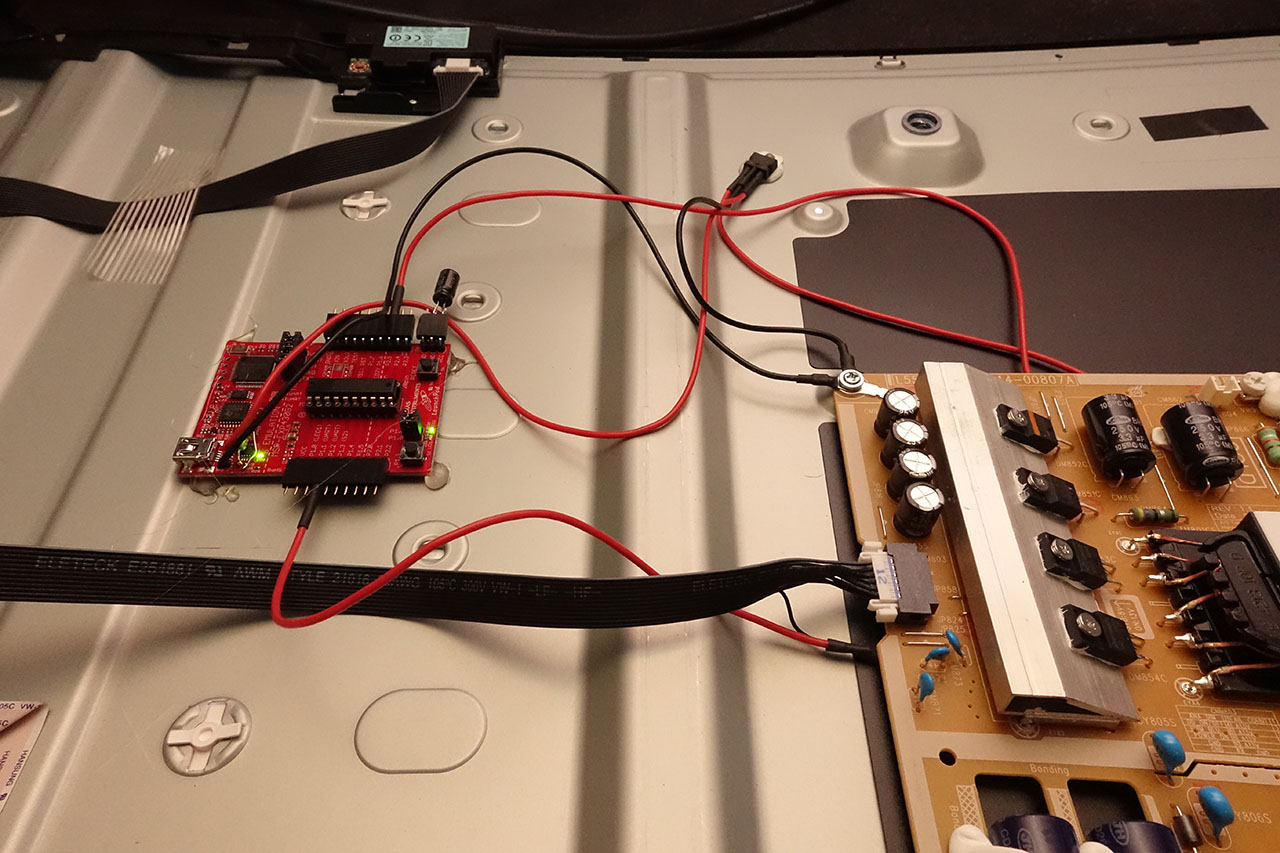
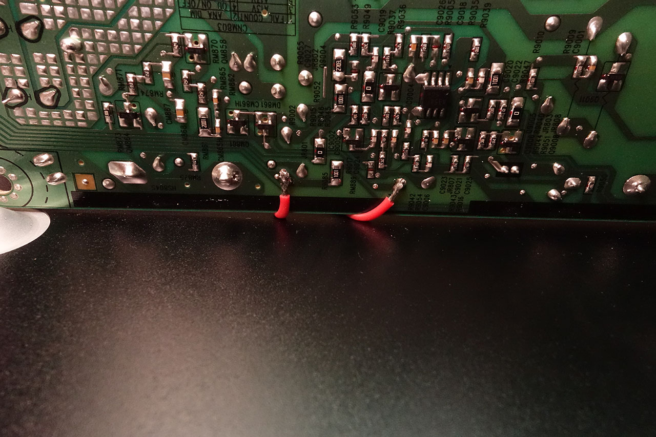
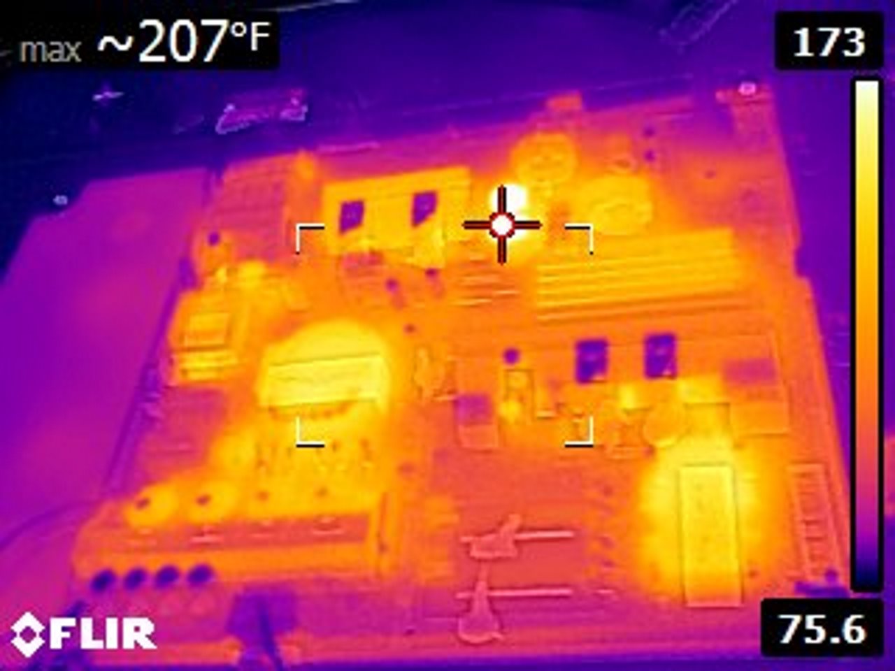
Basically, all the work is being done from the driver side of the tv. The original PWM pin was pulled from the connector and soldered to another wire going to the microcontroller. There is a pad that receives the same PWM signal near the top of the PCB, so it was used to inject the modified PWM signal back into the driver, since the original wire was removed from the connector. There is an empty pad on the top of the driver PCB that gets 13V from the same location as the connector/ribbon cable, so it was used as a power source, and brought down to 5V with a linear regulator to get to a safer Voltage for the launchpad PCB. There are 5V sources on the mainboard, but I wanted to keep all wiring simple and not potentially overload another circuit. It would be easier to wire up straight to the microcontroller, after programming is tested and done, but the launchpad is cheap and small enough, so putting the entire thing in the TV works for me. The temperatures across the power/driver board didn't do much switching to 360Hz.
Last edited:
SlippinJimmy
Weaksauce
- Joined
- Mar 29, 2015
- Messages
- 104
I just turned on a 50JU6500. I checked NVidia control panel, and I was set to 3840x2160 at 30hz, so I changed it to 60. Does that definitely mean I'm running at 60hz now?
I have to say that Amazon was wrong about the dimensions of the stand. I could have fit a 55 on my desk, but I couldn't really decide between the 50 or that model, anyway.
I have to say that Amazon was wrong about the dimensions of the stand. I could have fit a 55 on my desk, but I couldn't really decide between the 50 or that model, anyway.
Last edited:
SlippinJimmy
Weaksauce
- Joined
- Mar 29, 2015
- Messages
- 104
For the JU6500, should automotionplus be turned off for games and shows? Also, is there a post with the optimal settings? Not sure what to change it to, but at least I got 4:4:4 working.
I tried out Mario Kart 8 and it looked terrible from 3 feet away, unlike games with a 2160p setting. At least it looked decent from 6 feet.
I tried out Mario Kart 8 and it looked terrible from 3 feet away, unlike games with a 2160p setting. At least it looked decent from 6 feet.
Last edited:
In any case, 360Hz is better than nothing. I have some thermal imaging pictures of the driver board before and after the modification, and have noted the areas that have increased in temperature by about 20 degrees Fahrenheit - nothing that I think I need to worry about. I'm sure someone could spend countless hours getting more details, but this will have to work for me.
Basically, all the work is being done from the driver side of the tv. The original PWM pin was pulled from the connector and soldered to another wire going to the microcontroller. There is a pad that receives the same PWM signal near the top of the PCB, so it was used to inject the modified PWM signal back into the driver, since the original wire was removed from the connector. There is an empty pad on the top of the driver PCB that gets 13V from the same location as the connector/ribbon cable, so it was used as a power source, and brought down to 5V with a linear regulator to get to a safer Voltage for the launchpad PCB. There are 5V sources on the mainboard, but I wanted to keep all wiring simple and not potentially overload another circuit. It would be easier to wire up straight to the microcontroller, after programming is tested and done, but the launchpad is cheap and small enough, so putting the entire thing in the TV works for me. The temperatures across the power/driver board didn't do much switching to 360Hz.
That's amazing. Too bad that modification is way beyond most folks abilities. there's no technical reasons for the 120PWM, So I wonder why they chose 120.
For the JU6500, should automotionplus be turned off for games and shows? Also, is there a post with the optimal settings? Not sure what to change it to, but at least I got 4:4:4 working.
I tried out Mario Kart 8 and it looked terrible from 4 feet away, unlike games with a 2160p setting. At least it looked decent from 6 feet.
The Wii U is a 720P machine. It will obviously not compare to a 4k resolution. 720P is unplayable at that size and distance. If you're not doing any critical color work, I'd just use the eye ball test. It has always worked for me. Accuracy doesn't always look great.
Wii U does 1080p and for me looks great. I play Smash with a bunch of friends and it looks really good. I'm using game mode as well. Up to five feet away it looks crisp. The closer you get after that, you can tell it is upscaled but we normally sit around six feet+ away anyways when playing.
Wow SGSeeker - awesome post!! So? Was it worth it? Your eyes happier? Too early to tell? PWM sensitivity can vary depending how long you've been staring vs. a set of fresh eyes etc. let us know. I'd think 3x'ing the freq would be great.
Worth it? Not as worth it as 2KHz PWM, but I can use brightness level 5 (good setting for a dark room) without any noticeable flickering. I think level 8 gives the best whites in a dark room, and level 12 is good for sunlit rooms, or a few light bulbs. I think one PWM gets over ~240Hz, it starts to become much less noticeable or fatiguing to people. 1KHz is around the area where even the most sensitive claim they can no longer see any pwm, specifically looking for it. I think 360Hz is fine - the display in a dark room at low brightness no longer reminds me of a 60Hz CRT monitor. The picture appears more stable. A lower frequency is far nicer to the LED driver also.
That's amazing. Too bad that modification is way beyond most folks abilities. there's no technical reasons for the 120PWM, So I wonder why they chose 120.
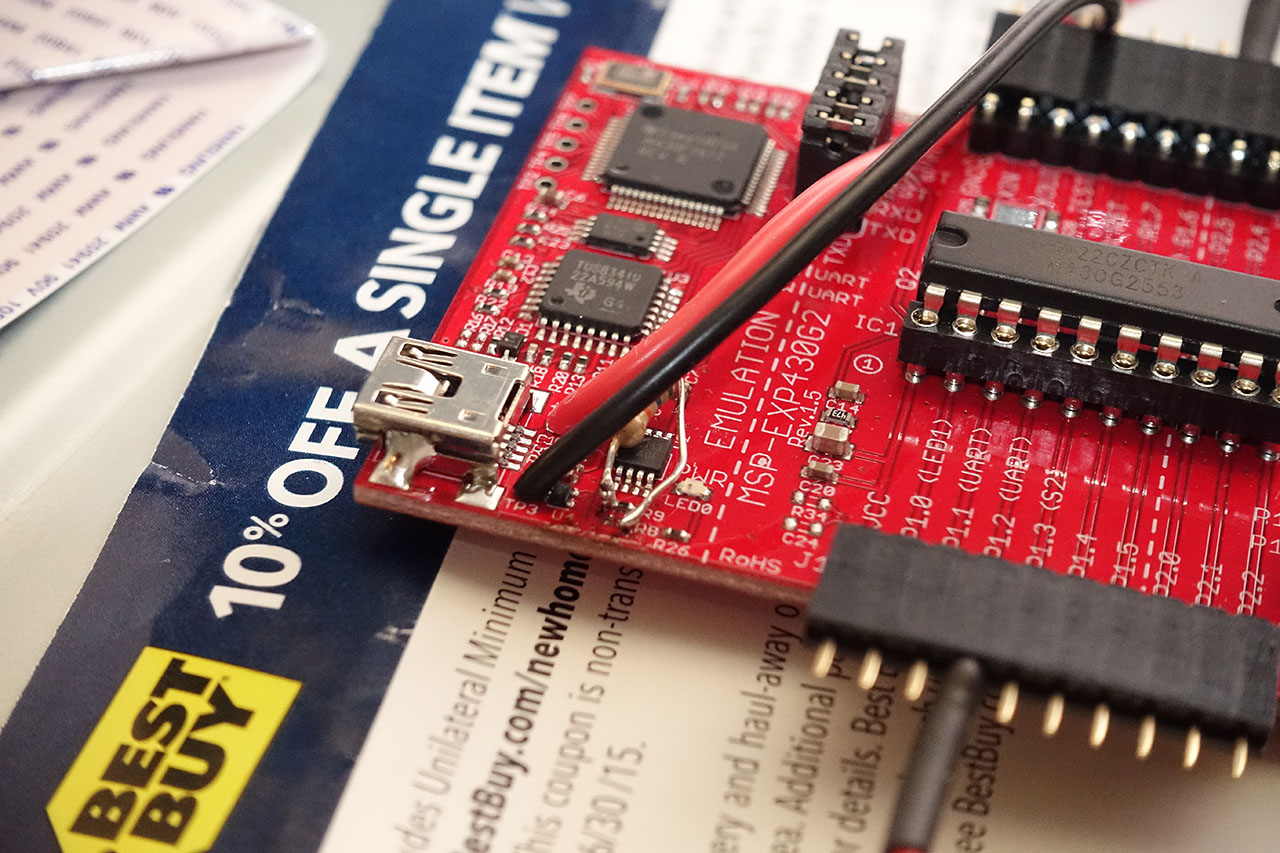
I think if most people had a pre-programmed chip, they could do the mod easily. You just solder four wires to a chip socket (power, ground, pwm in, pwm out), pull a pin from one connector (tiny screwdriver) on the tv, solder 2 wires to the TV's power supply PCB, one wire to the ping pulled from the connector, and add a regulator + capacitor in between power and socket to give the MSP430G2553 3.3V. None of it even needs a PCB.
The launchpad was just annoying to deal with as changing a tiny surface-mount resistor to a different (physically larger) resistor, installed to the same pads, was quite difficult. It wasn't THAT bad, but the hardest part of the mod for sure. Everything else just popped into place without a second try. The resistor had to be resoldered a couple times. This resistor isn't even needed if not using the launchpad PCB.
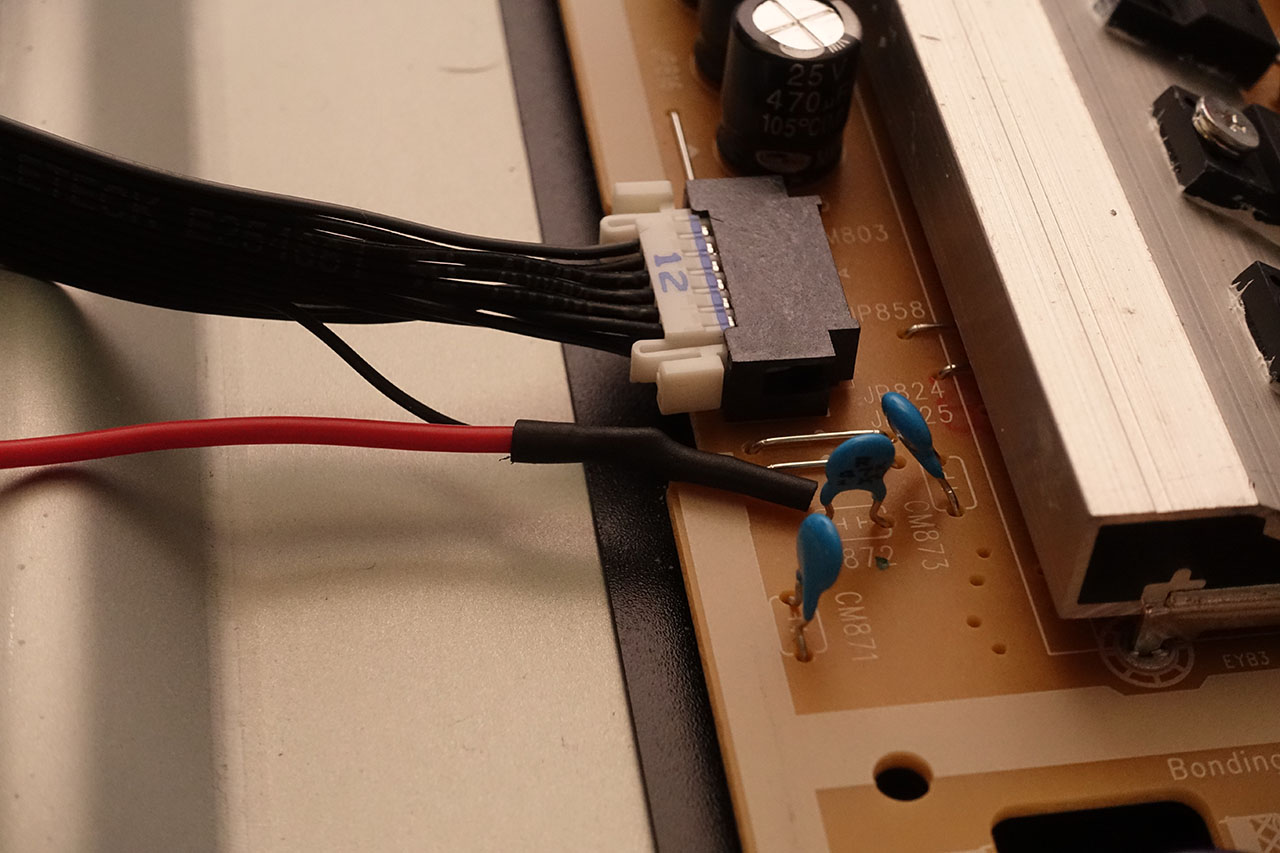
The back of the tv opens up by simply removing the stand, then over a dozen other screws and the plastic cover lifts right off. The power supply board also comes out for soldering simply by disconnecting two squeeze-and-pull connectors and removing 5 screws.
If a replacement cable could be sourced, it would be modified to have the PWM wire cut, along with a 13V and ground wire to have a wire tapped into each. Everything that is needed is contained in the ribbon cable.
If someone was in Oregon or Washington and wanted to give this a mod a try on their display (Portland area), I'm sure we could find a more user-friendly way of doing the mod. It would likely involve a pre-programmed chip, a socket, a capacitor, a 3.3V regulator, a replacement ribbon cable (plug and play), and a few pieces of extra wiring. Just tape or glue in place, and you have a display that can be returned to factory form by simply swapping the original cable back in. The entire plug and play harness would probably take 30 minutes to build one-offs, and 10 minutes to build if making a batch. Parts are under $10, plus ribbon cable.
The current code isn't great at auto-backlight dimming, even when sped up to a quicker sample rate, so that feature would need to be disabled.
Last edited:
DarkStar02
2[H]4U
- Joined
- Mar 1, 2006
- Messages
- 2,144
Worth it? Not as worth it as 2KHz PWM, but I can use brightness level 5 (good setting for a dark room) without any noticeable flickering. I think level 8 gives the best whites in a dark room, and level 12 is good for sunlit rooms, or a few light bulbs. I think one PWM gets over ~240Hz, it starts to become much less noticeable or fatiguing to people. 1KHz is around the area where even the most sensitive claim they can no longer see any pwm, specifically looking for it. I think 360Hz is fine - the display in a dark room at low brightness no longer reminds me of a 60Hz CRT monitor. The picture appears more stable. A lower frequency is far nicer to the LED driver also.
I think if most people had a pre-programmed chip, they could do the mod easily. You just solder four wires to a chip socket (power, ground, pwm in, pwm out), pull a pin from one connector (tiny screwdriver) on the tv, solder 2 wires to the TV's power supply PCB, one wire to the ping pulled from the connector, and add a regulator + capacitor in between power and socket to give the MSP430G2553 3.3V. None of it even needs a PCB.
The launchpad was just annoying to deal with as changing a tiny surface-mount resistor to a different (physically larger) resistor, installed to the same pads, was quite difficult. It wasn't THAT bad, but the hardest part of the mod for sure. Everything else just popped into place without a second try. The resistor had to be resoldered a couple times. This resistor isn't even needed if not using the launchpad PCB.
The back of the tv opens up by simply removing the stand, then over a dozen other screws and the plastic cover lifts right off. The power supply board also comes out for soldering simply by disconnecting two squeeze-and-pull connectors and removing 5 screws.
If a replacement cable could be sourced, it would be modified to have the PWM wire cut, along with a 13V and ground wire to have a wire tapped into each. Everything that is needed is contained in the ribbon cable.
If someone was in Oregon or Washington and wanted to give this a mod a try on their display (Portland area), I'm sure we could find a more user-friendly way of doing the mod. It would likely involve a pre-programmed chip, a socket, a capacitor, a 3.3V regulator, a replacement ribbon cable (plug and play), and a few pieces of extra wiring. Just tape or glue in place, and you have a display that can be returned to factory form by simply swapping the original cable back in. The entire plug and play harness would probably take 30 minutes to build one-offs, and 10 minutes to build if making a batch. Parts are under $10, plus ribbon cable.
The current code isn't great at auto-backlight dimming, even when sped up to a quicker sample rate, so that feature would need to be disabled.
That's awesome. I hope you find someone to meet up with, I'd definitely be interested in a kit.
seanclayton
Gawd
- Joined
- Oct 25, 2008
- Messages
- 882
Just so you guys know, prices on the higherend models are dropping like flies now.
http://www.bestbuy.com/site/searchp...t=n&iht=y&usc=All+Categories&ks=960&keys=keys
Very tempting to return the Panny, but I dunno.
http://www.bestbuy.com/site/searchp...t=n&iht=y&usc=All+Categories&ks=960&keys=keys
Very tempting to return the Panny, but I dunno.
That's awesome. I hope you find someone to meet up with, I'd definitely be interested in a kit.
I'd like to have more time inside a display, but don't want to tear mine back down again right now. The flickering/signal failure at 2Khz wasn't much more frequent than at 480Hz. I'm curious if the driver is really sensitive to the input signal, and how it would behave if I gave it 3.2V instead of 3.3V. 3.3V is only used as the original signal coming from the mainboard is 3.3V. I'm not sure how much Voltage for the pwm signal the driver is capable of taking. The signal looked great on the oscope, but it may be an issue where even 0.1V could be a huge change in how the driver reacts to how high of a frequency it reacts to. That or the driver just can't switch fast enough, although again, it worked for thousands of switches before it'd fail on a pulse or two, and work again.
The display would flicker every 5-10 seconds, sometimes once, sometimes twice within a second, looking like a pwm signal to the backlight was missing for only millisecond.s Looking at the information at the end when using a solar panel to measure backlight output (when tuning below 600Hz), the pulse would sometimes appear to be slow to build to max output, but enough to notice the display "flicker"/dim out very briefly (we're talking single-digit milliseconds here).
If I can find the ribbon cable/part number (marked "12", for 12 pins. It has two rows of 6 pins.), I'd be willing to open mine back up and try building a simpler mod. A person can still program the microcontroller remotely doing it this way, so it can still be built and tested/tuned without needing to move the chip between the programmer board and final socket.
Last edited:
Megalith
24-bit/48kHz
- Joined
- Aug 20, 2006
- Messages
- 13,000
Is Best Buy not carrying the 40" versions?
TheDarkTao
Gawd
- Joined
- Feb 5, 2005
- Messages
- 800
has anyone seen reviews on the js8500??? Very curious
black88mx6
n00b
- Joined
- Mar 4, 2012
- Messages
- 21
Is Best Buy not carrying the 40" versions?
All but the 7500.