jedihobbit
Gawd
- Joined
- Nov 3, 2005
- Messages
- 963
Due to being fickle and determined by the fates, DreamCatcher has again morphed and I decided to attempt one last worklog. The original last build was supposed to be DreamCatcher v3.0. However with me not making up my mind as to what was going to go where (especially with several new components showing up); all of my builds went through several changes (on paper thanks goodness!). Ultimately this lead to DC no longer being top dog
.and it has received a parallel transfer.
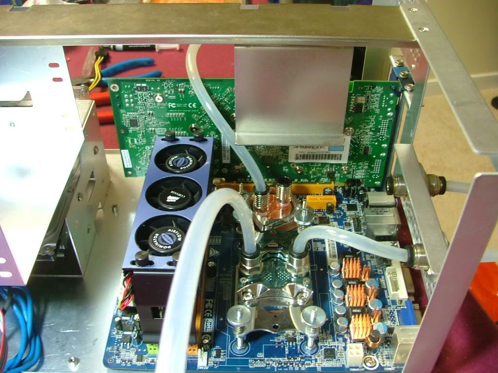
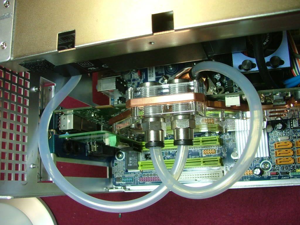
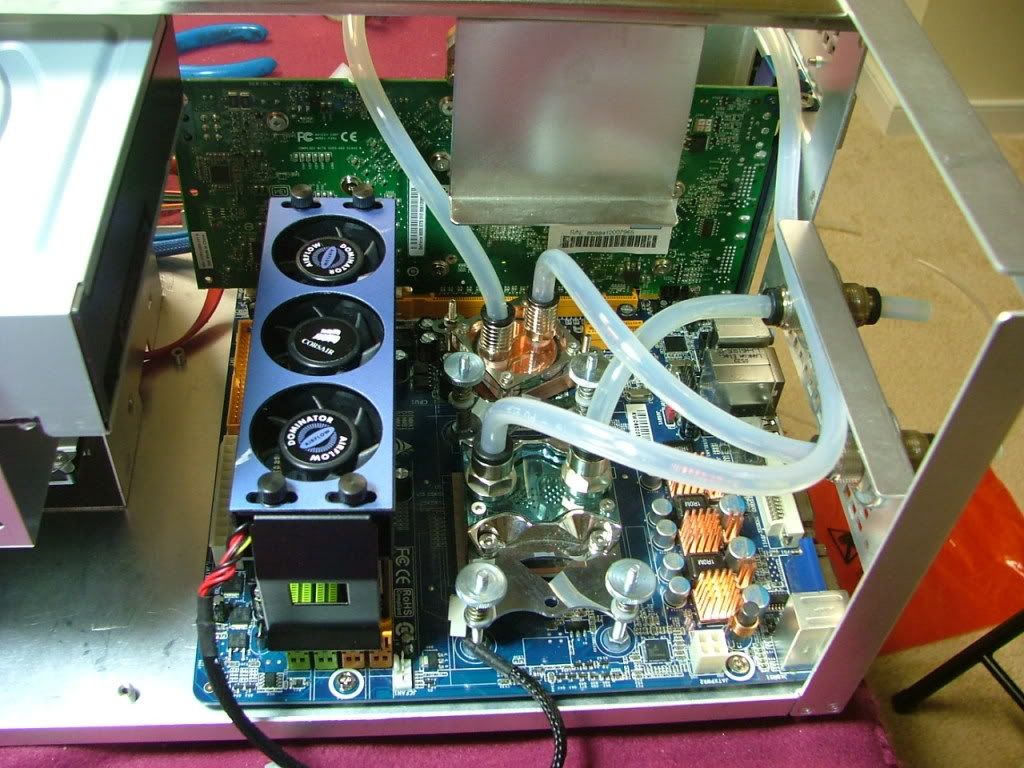
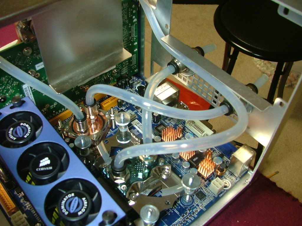
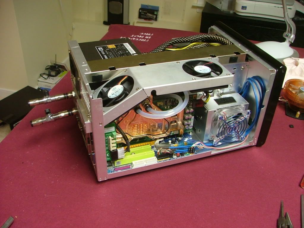
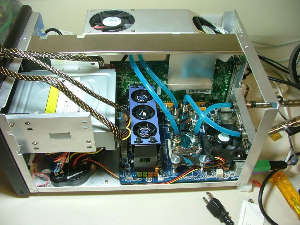
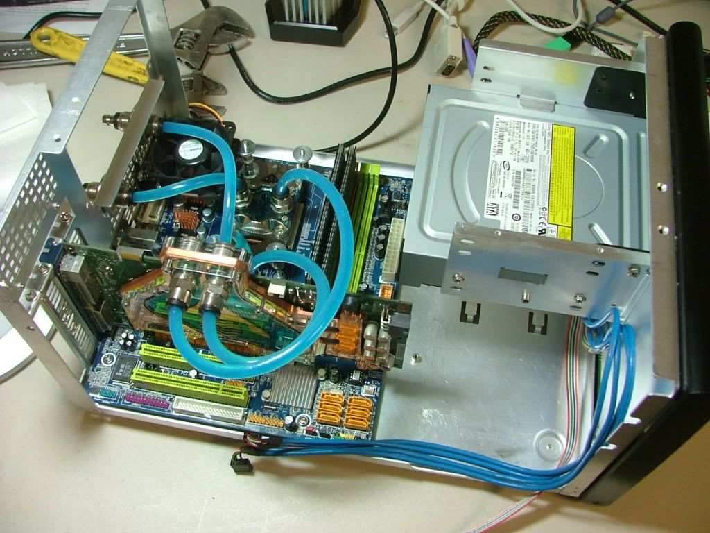
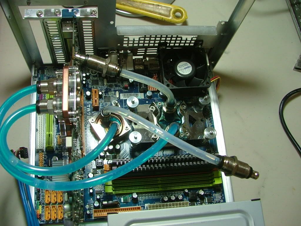
After much hem and hawing it was decided to keep DC as the bling water cooled system, but it changed positions with Kermit the Folder. Since the mobo/proc assembly has changed and it will be my primary SMP folder this will be DreamCatcher v3.5. Much thought went into this as originally it was slated to receive the Asus M3A78-CM / Kuma 7750BE. I felt that if DC v3.5s primary mission was to look pretty and be water cooled a tri-core would make more sense. Had thought of including the GTX 260-216 also but couldnt afford the water block. Here are the mechanicals:
CASE: SilverStone SOG1
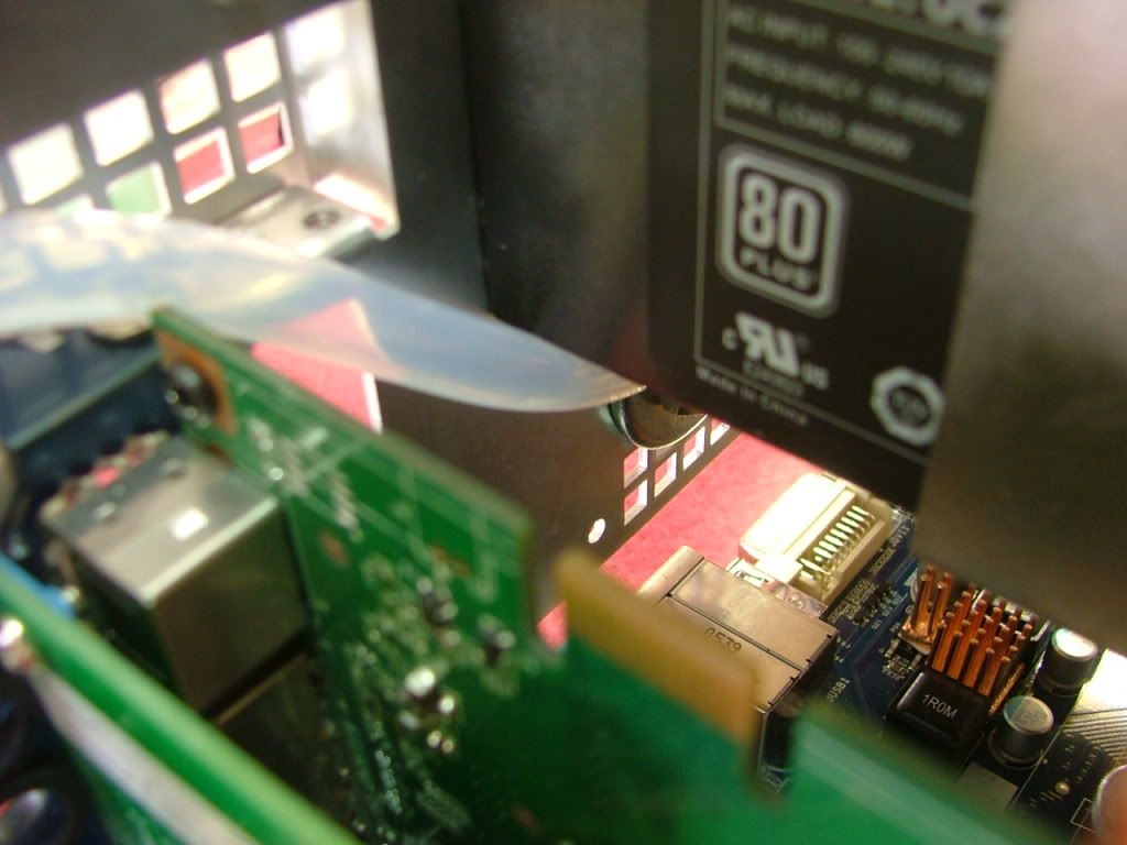
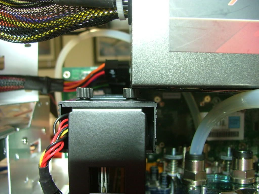
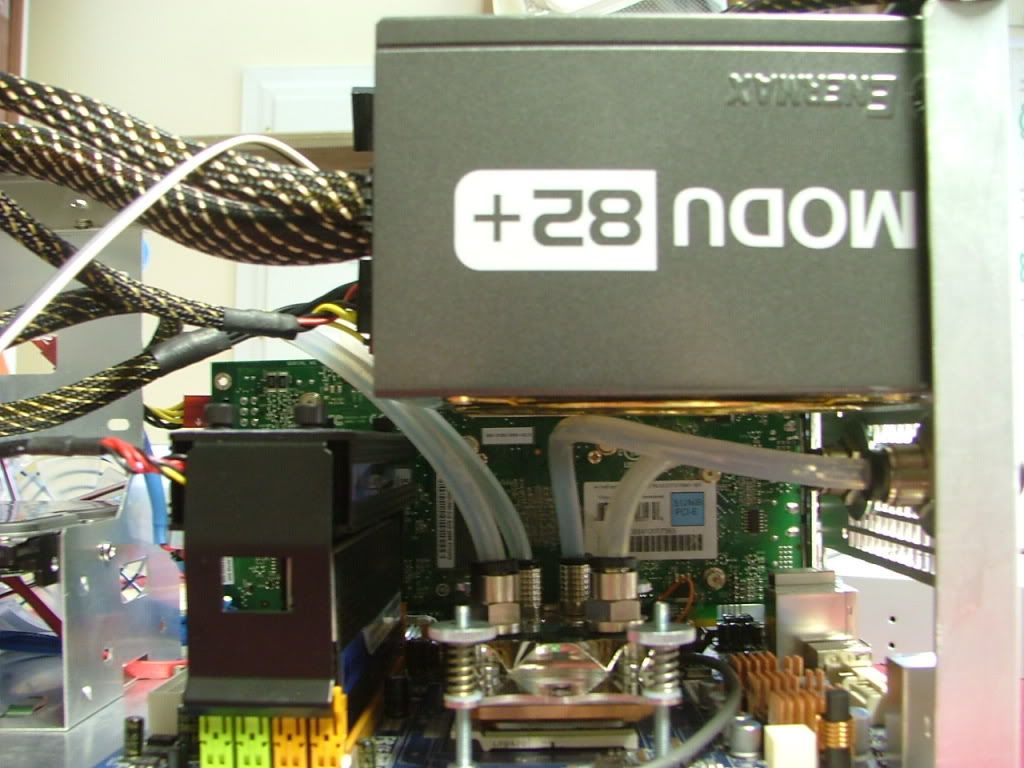
PSU: Enermax Infiniti 650W
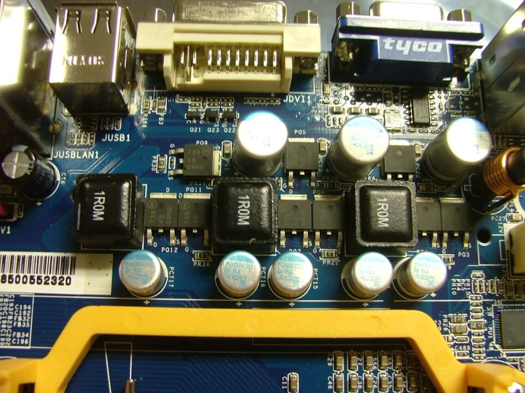
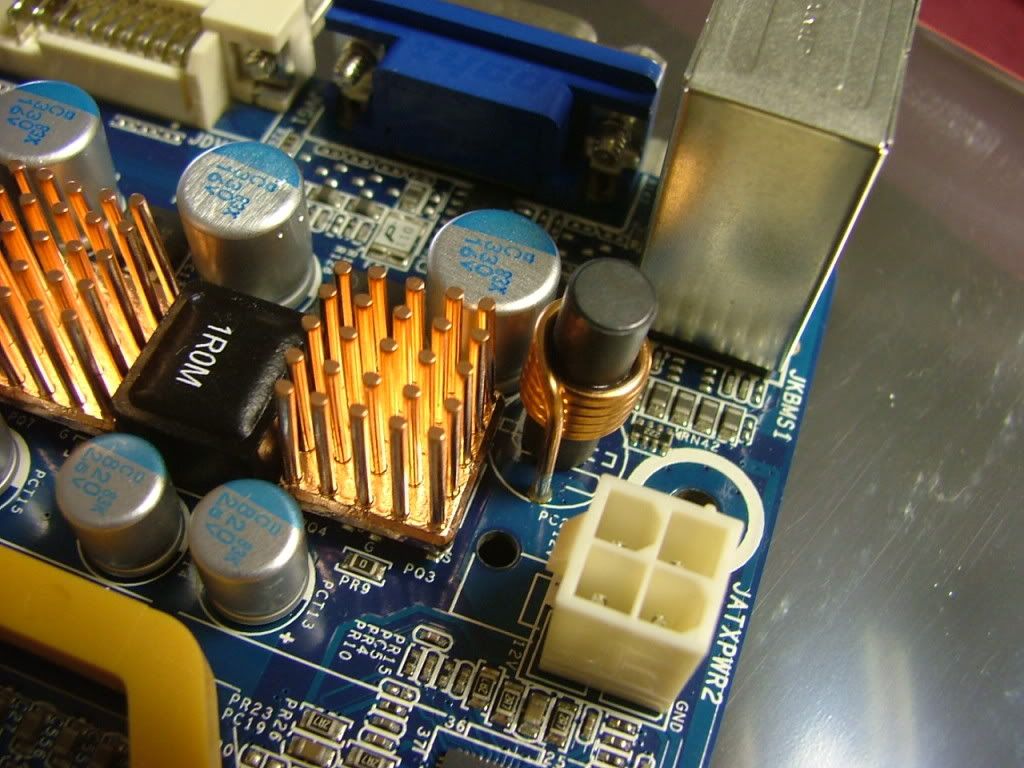
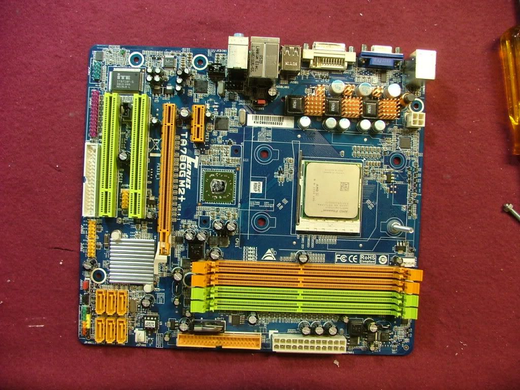
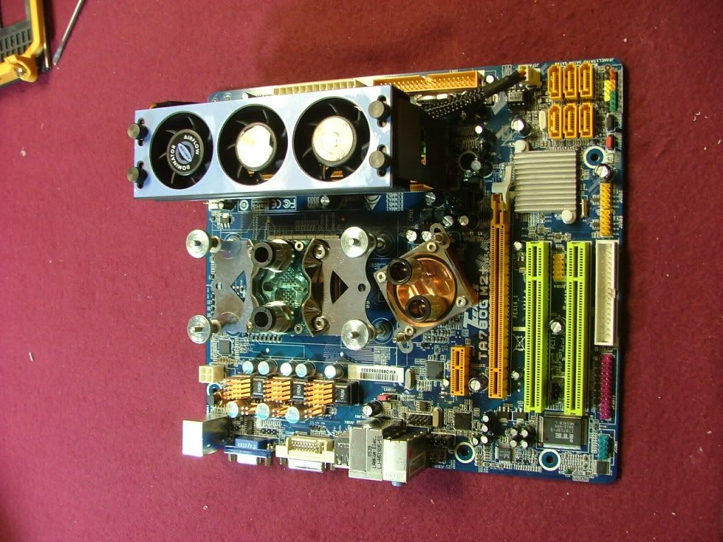
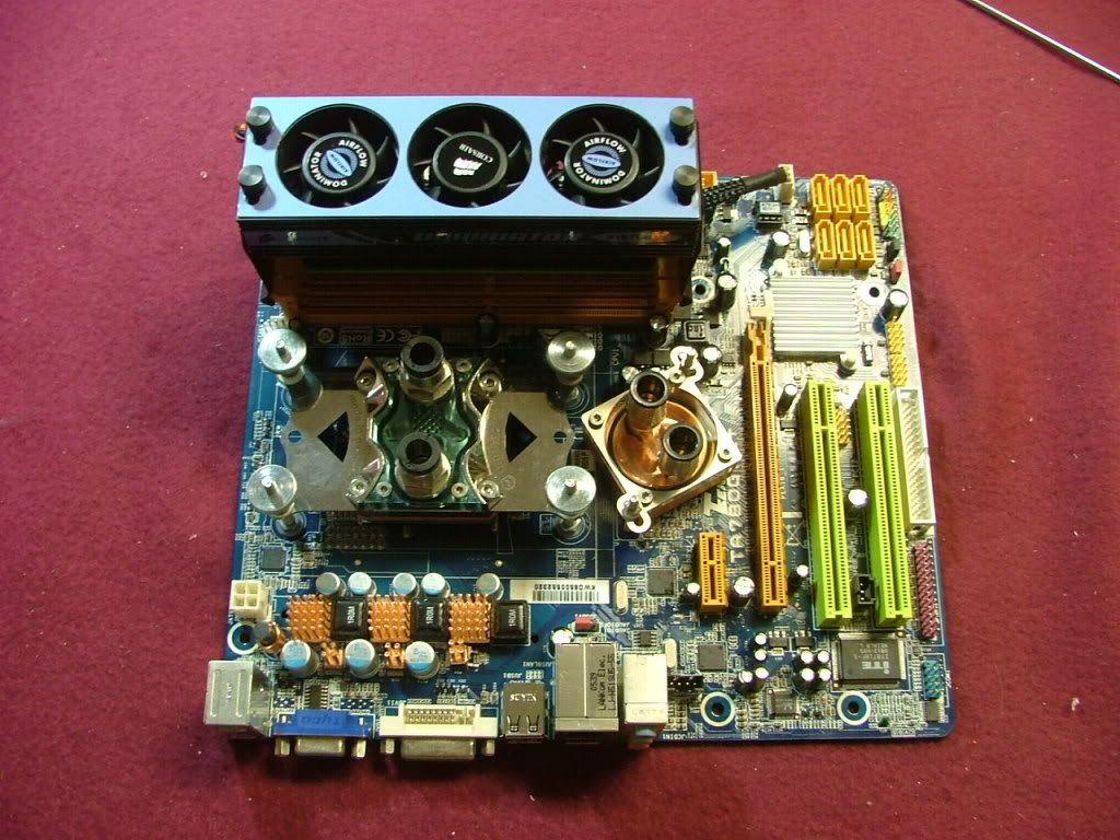
MOBO: Biostar Tf780G AM2+
CPU: AMD PI X3 8750BE
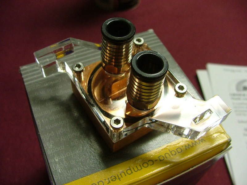
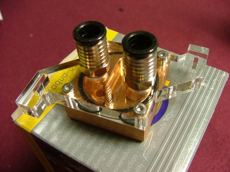
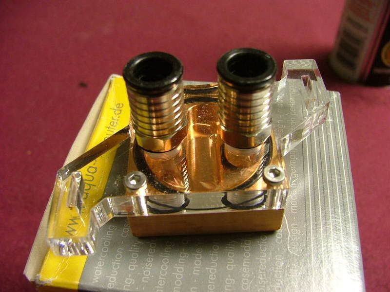
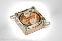
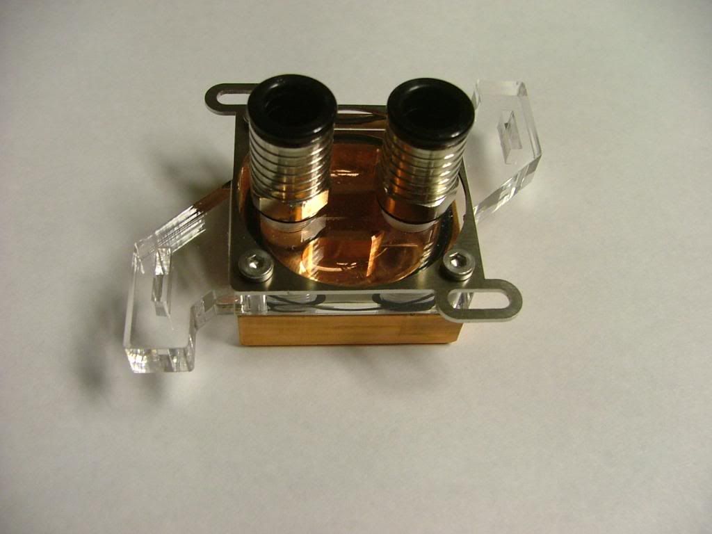
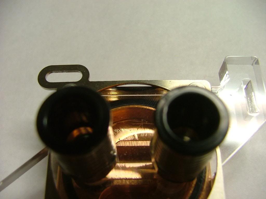
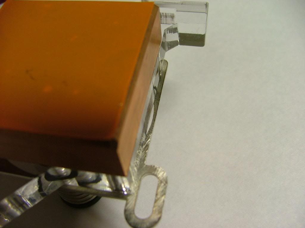
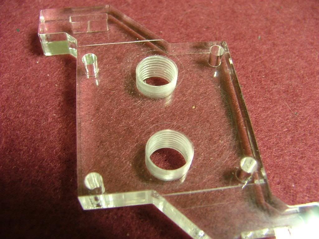
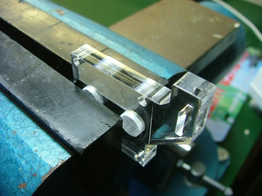
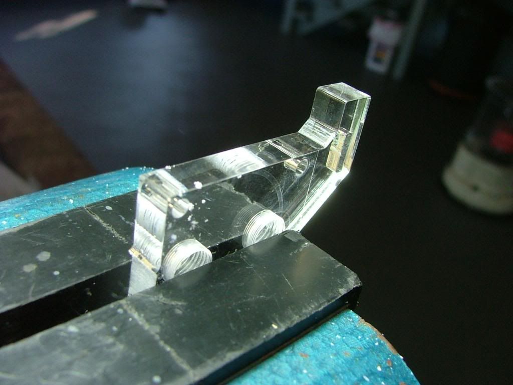
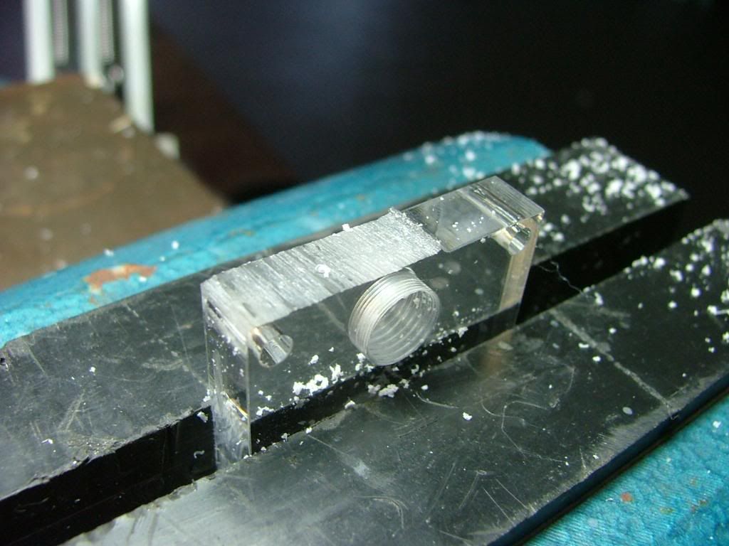
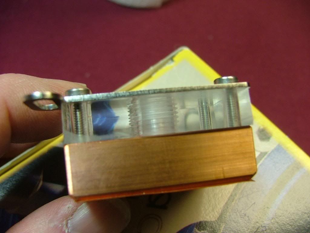
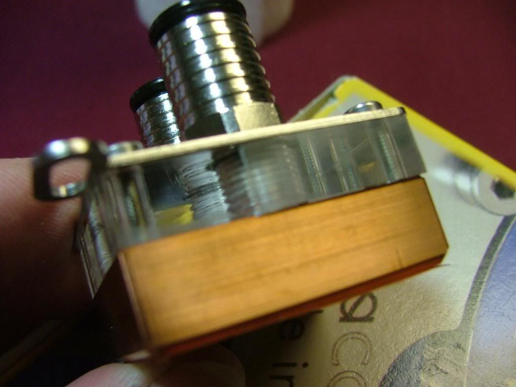
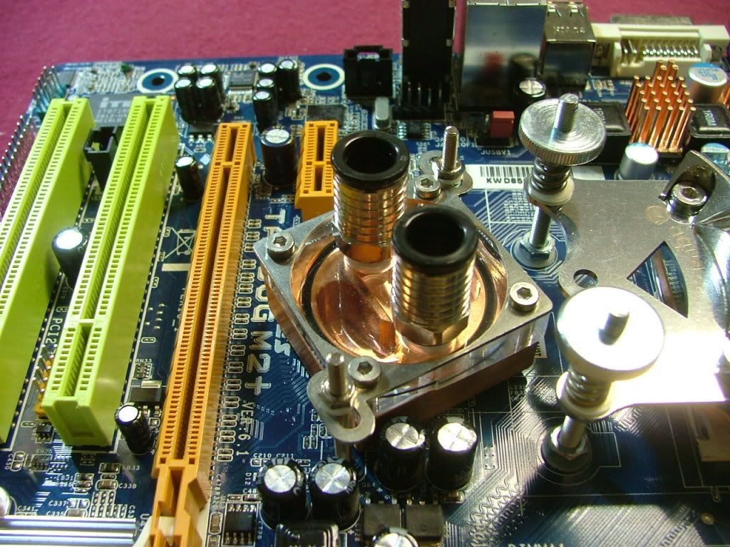
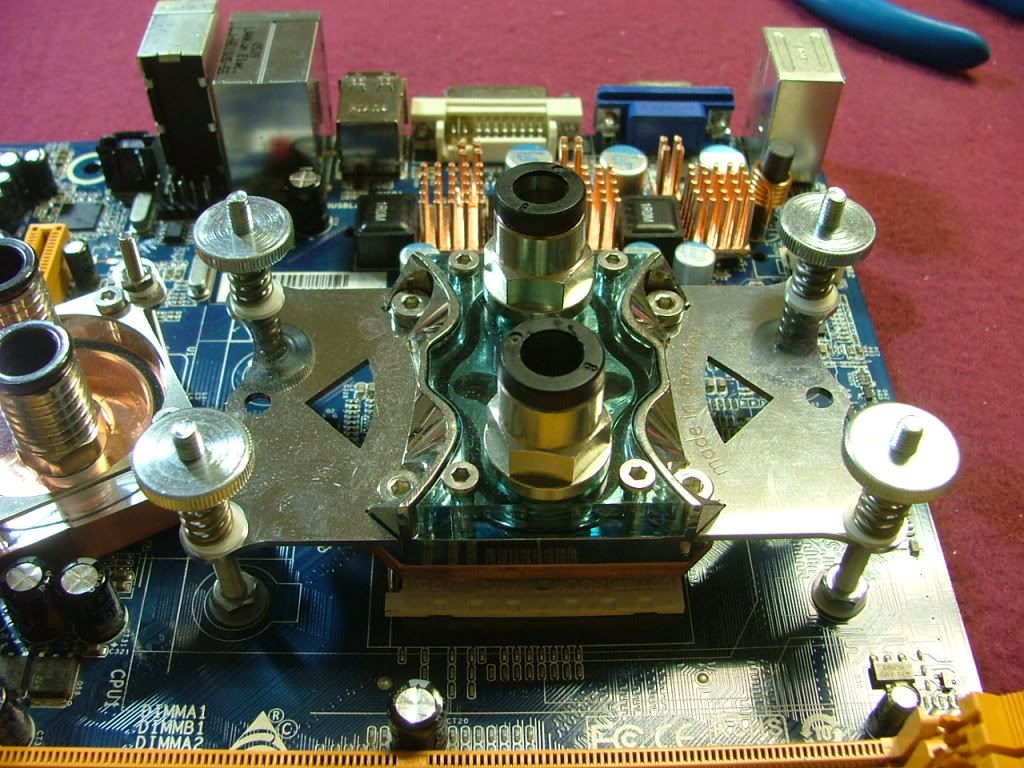
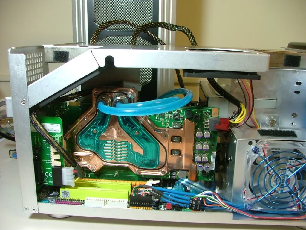
HSF: Cuplex XT di
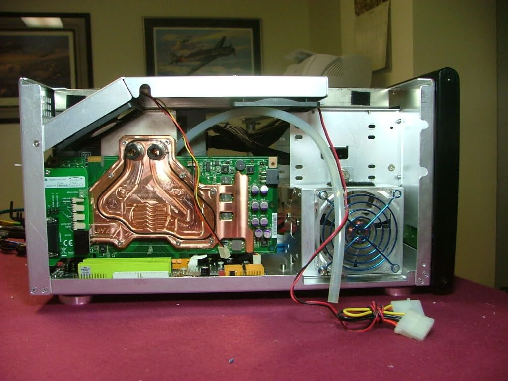
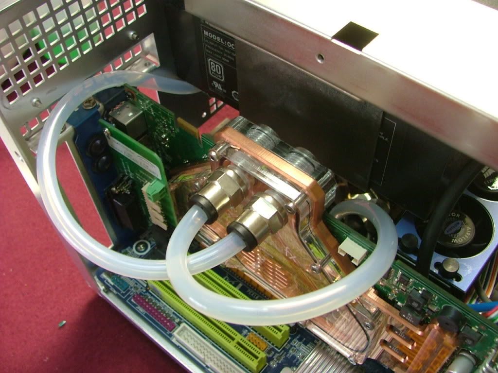
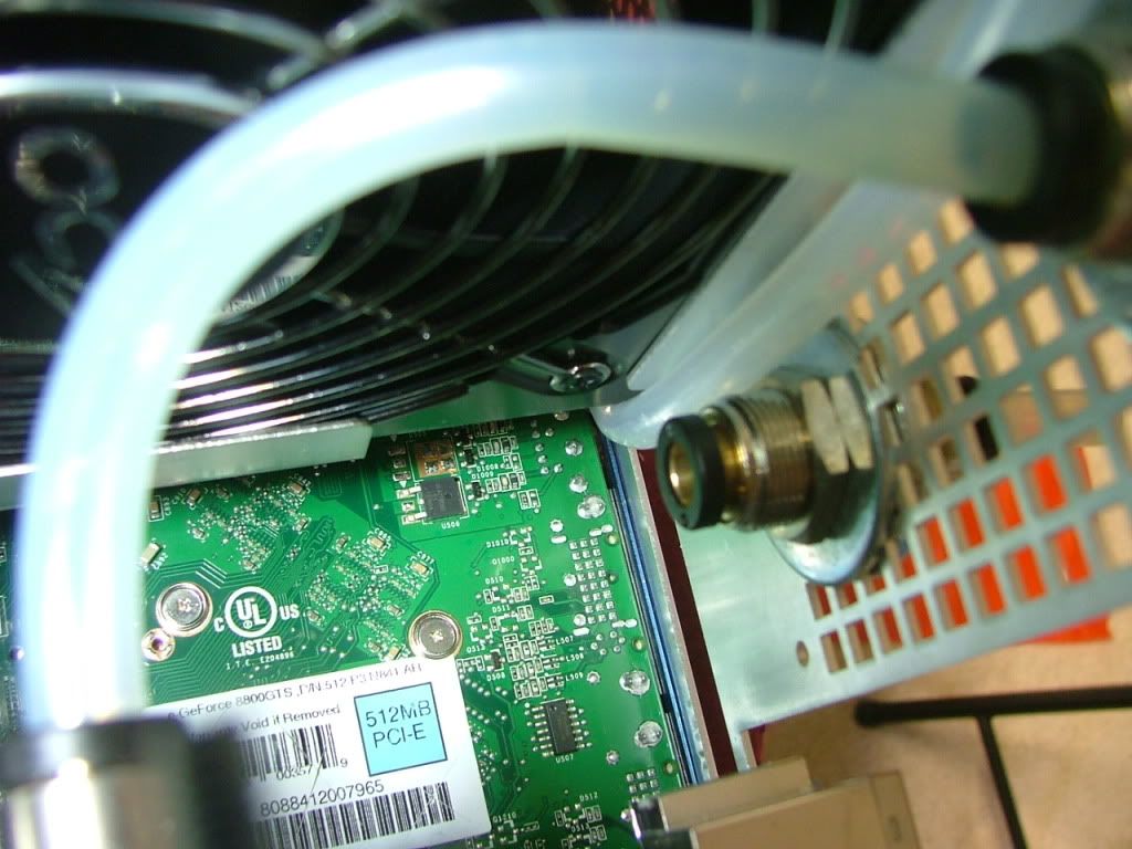
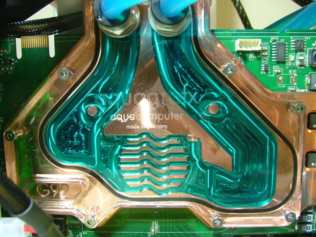
GPU: Evga 8800GTS w/AquagraFX 8800
MEMORY: TWIN2X2048-8500C5DF
HDD: Seagate 7200.10 ST380815AS 80GB
Optical Drive 1: Soney NEC Optiarc AD-7200S
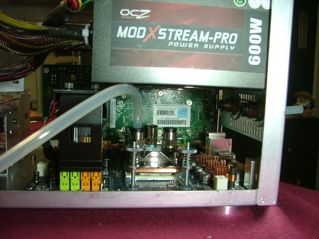
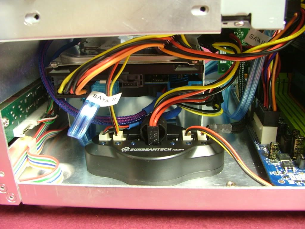
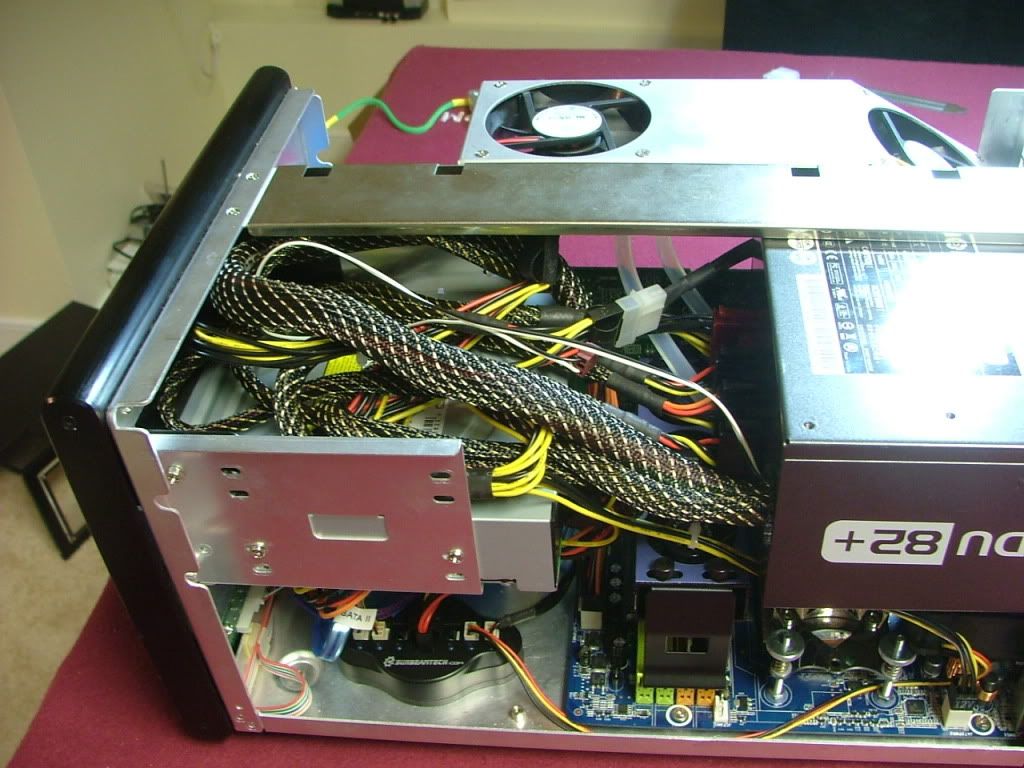
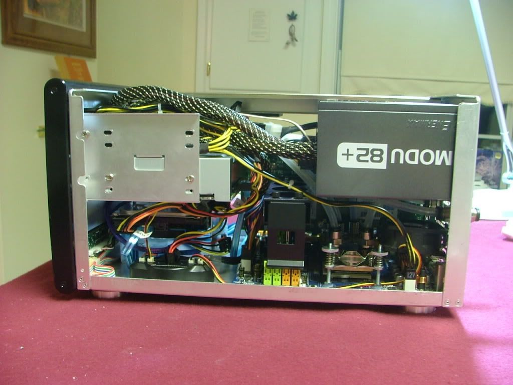
A lot of things occurred between v2.0 and the now v3.5, hopefully Ill present it in a meaningful manner. One of the reasons the MX6 case was dropped is primarily due to wanting a full coverage water block for the GPU. In the MX6 the PSU is directly above the vid card which precluded using the one I wanted. In the SG01 the PSU has been moved above the CPU giving me the extra room required.
February, 2009
The case was bought used and the prior owner cut a window in the side and apparently had a rad screwed to the top. These are his pictures and yes the dust was free!
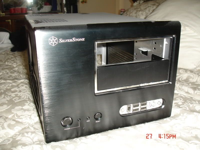
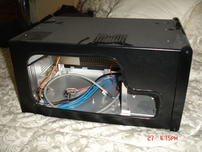
Something the prior owner must not have taken in to consideration when doing the window is how little space there is between an interior window and the frame. Edging had been used to cover the cut, but if one was to attach a piece of plex for a window with the edging in place it would not have fit.
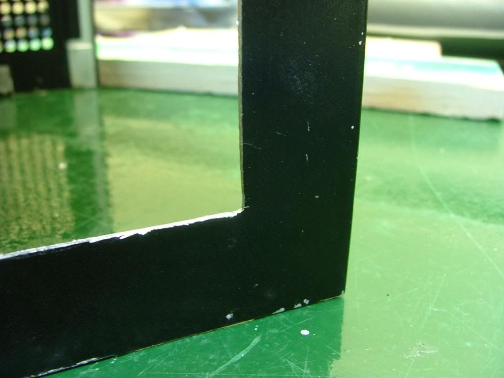
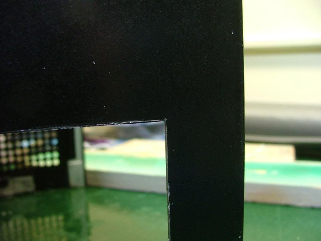
So I removed the edging and found a pretty good edge for the cutout. Where it was rough is in the bottom corners where the cooling holes are located. As you can see here .
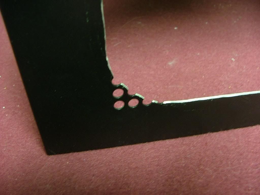
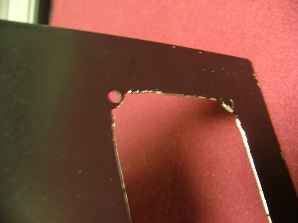
I decided to square the corners as best I could and file the rough areas to be the finished edge and attach the window behind. I now know why the SOG1 factory windows are mounted on the outside.
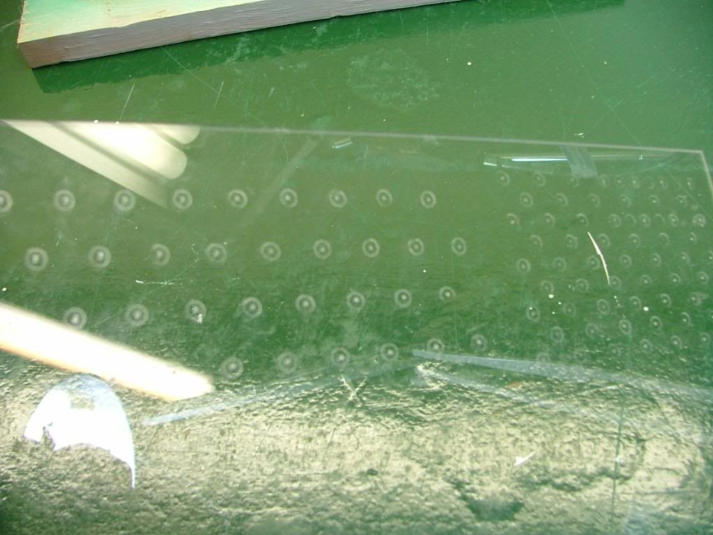
Had a spare piece of plex lying around so decided to do an engineering sample of the window. One of the big things in putting in that window is Ive lost all of the lower cooling holes .especially those required by the hdd cage fan.
I taped the plex to the opposite side and scribed holes based on it hole pattern. My spacing and sizing will be different as Im afraid of cracking the plex if the holes are too close. Decided on multiple small holes in the hdd area with fewer large holes (3/8) for the rest. Here you see the rough layout with center punches prior to drilling. The centers are eye-balled so it wont be all that nice and neat!
You may wonder why I call the window an engineering sample, quit simple .
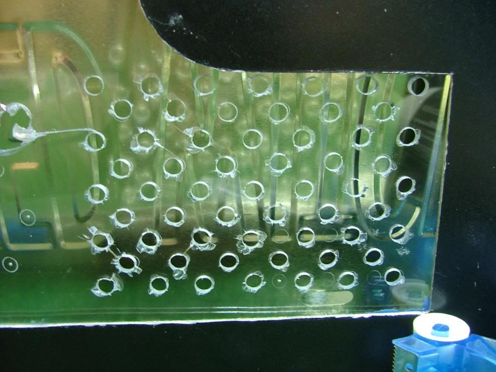
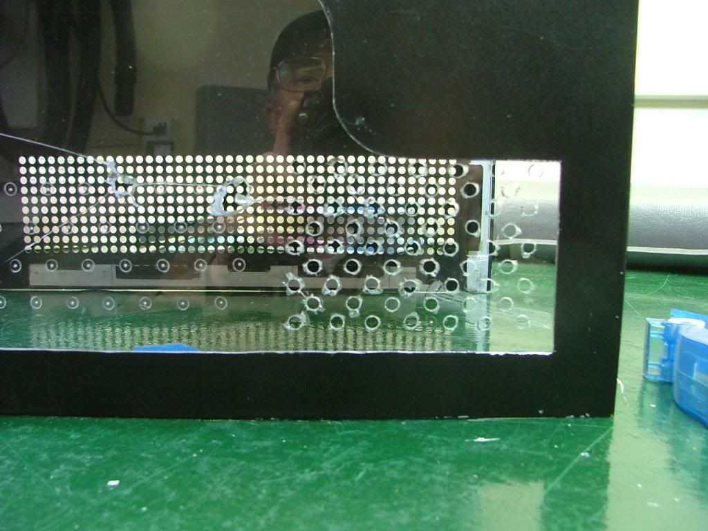
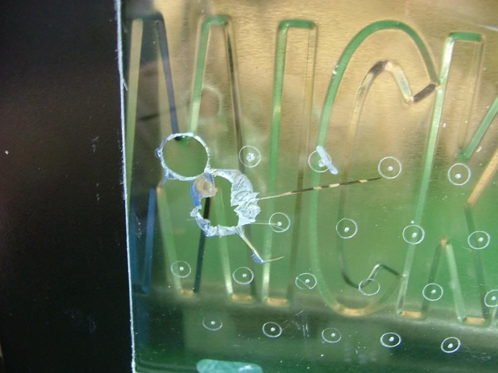
By experimenting on hole sizes and locations Ive saved a wee bit of heart break. You can see the material I have on hand is too brittle to drill. What I was able to do shows me the hole spacing is fine, but the pattern for the HDD fan needs to be lowered. Now to find some lexan to work with.
Needing to patch the holes in the top of the cover I drug out the stuff I used when doing the side panels of my original (unfinished and in the attic) Celtic Spirit.
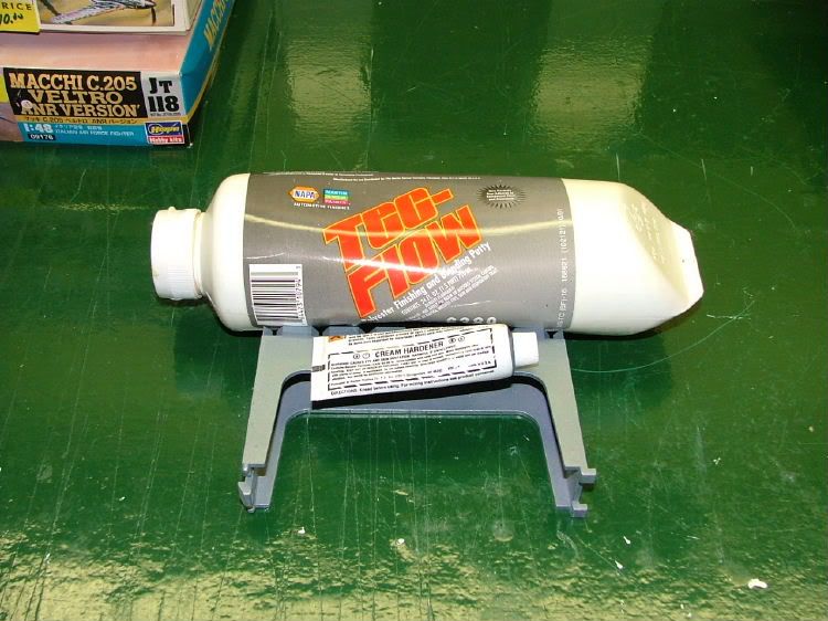
It is easy to use and I just hope not too old! Backed the holes using painters tape with the hopes of only needing to sand one side. It turns out I mixed too little catalyst requiring about 2 2-1/2 times longer to cure. Then it was sanding time!! Also took the opportunity to smooth out as best I could the edges of the window opening.
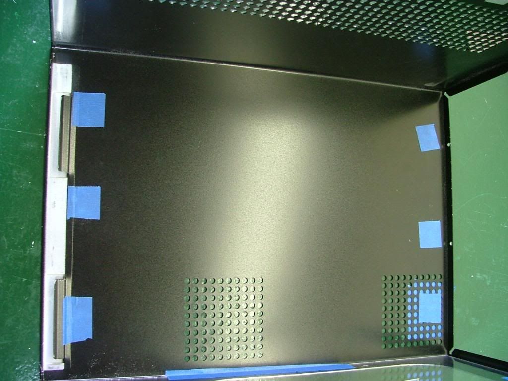
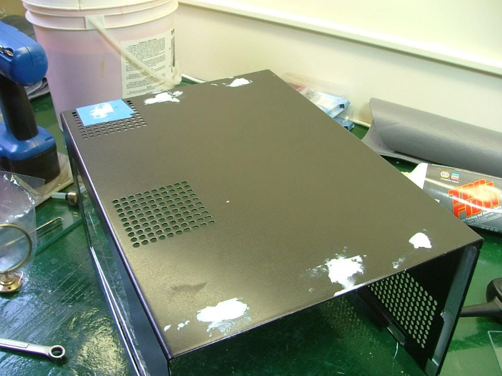
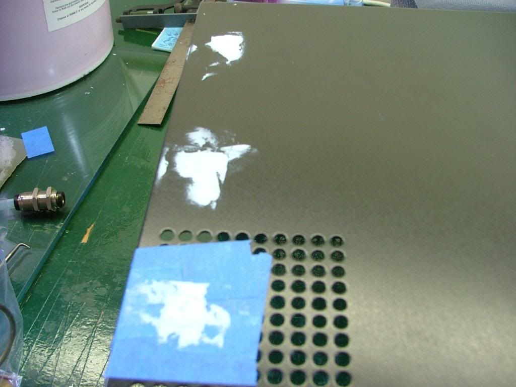
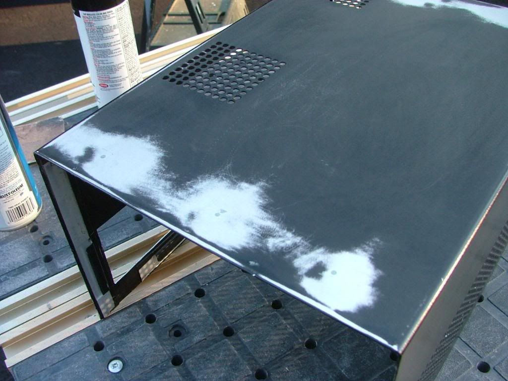
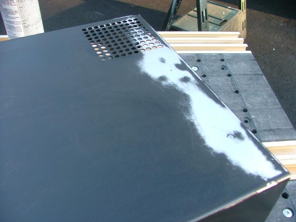
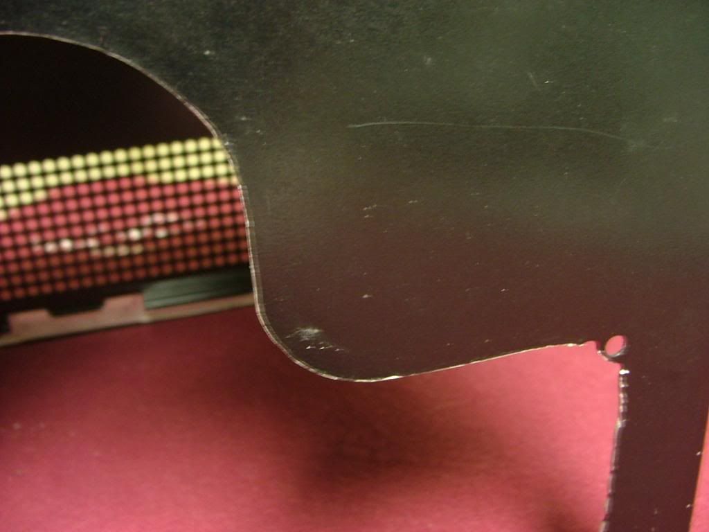
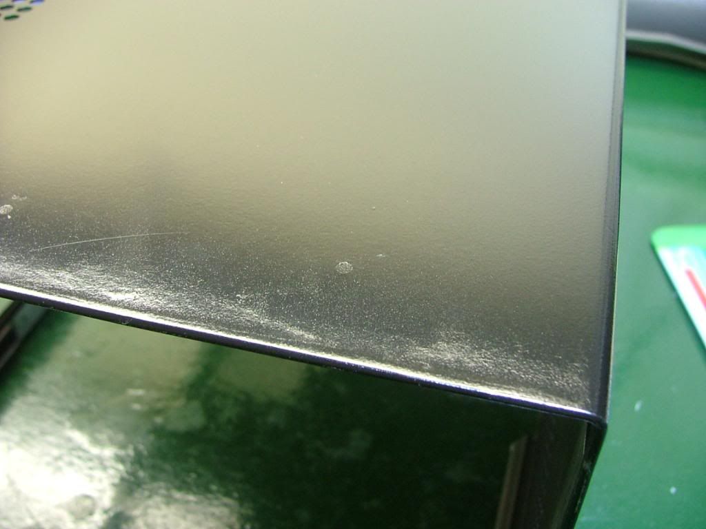
Here we are ready for painting after it was done it appeared to be fairly reflective. I jokingly referred to the method as quick and dirty because of doing in a few hours what should be done over several days. However in the last pic youll see the patched holes .which if done with primer and sufficient coats of paint one shouldnt see. Lets just say this isnt one of my better paint jobs and needs to be located in a dark area of the office!
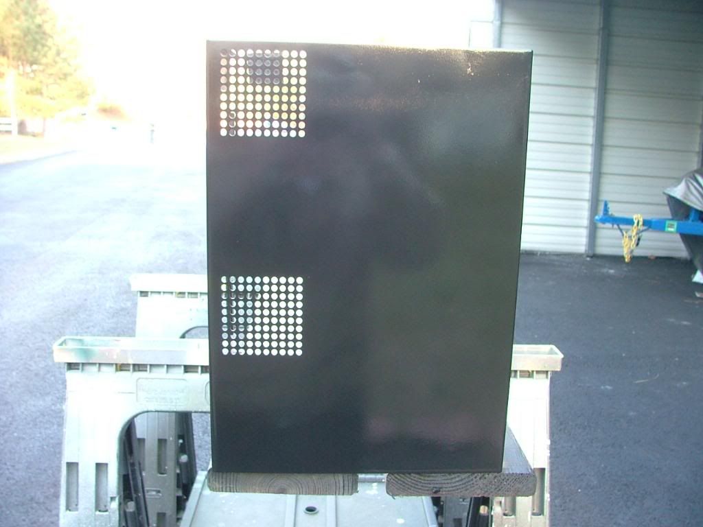

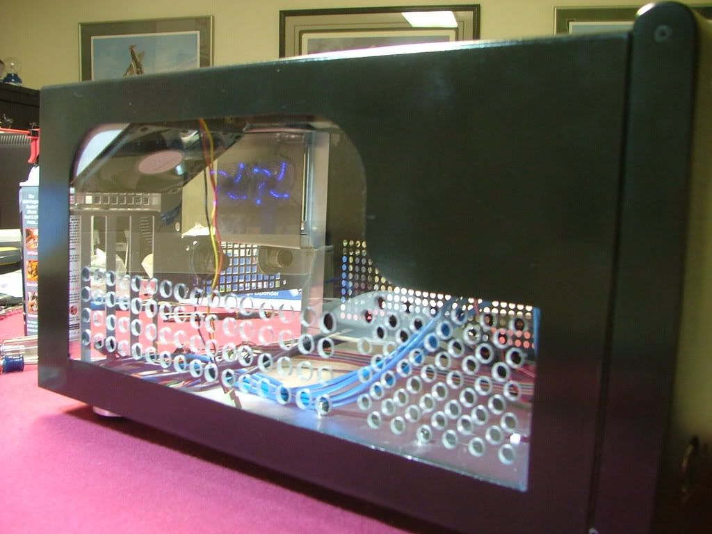
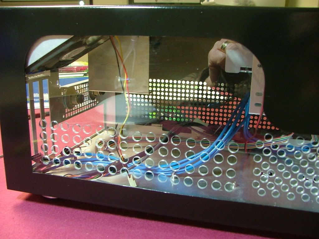
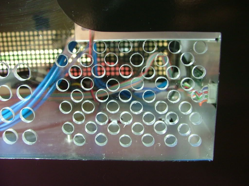
Finally got around to picking up a piece of Lexan for drill ability. The first few pictures I took are while laying out the hole patterns and beginning to drill. While it may appear somewhat inconsistent decided on two different size hole and patterns. You may notice the two stray holes up top that was a test in an area not seen. If you look closely youll see where the window edge is.
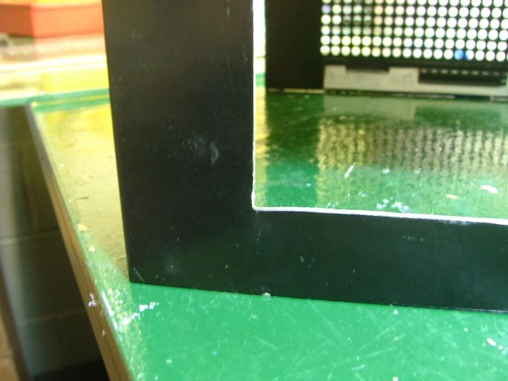
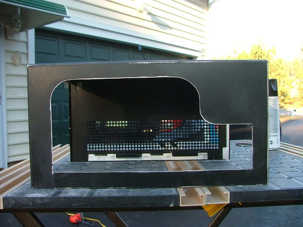
Lexan makes a big difference when it comes to drilling! It was easier by far over the plex but has it own minor issues. I was using a wireless drill at low speeds but it would still grab on occasions. Also I had difficulty in cleaning any rough edges and in the process managed to scratch the surface and will need to spend the time finding and using some glass polish. Here you have it temporarily mounted and in the closer views see some of the needed clean up.
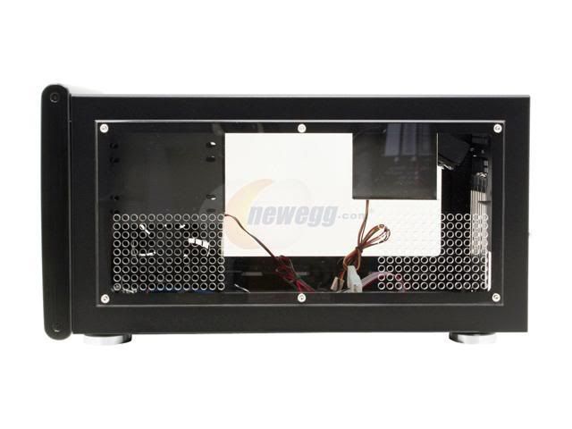
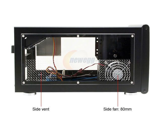
As a safety valve I did manage to pick up a factory windowed cover as I wasnt sure how to do a window the right side. Wanted to have windows on both sides as the coolant is UV reactive and Ill be installing a pair of UV laser light fixtures. Also need to go back and do a little hammer, grind, and file to suit on the custom window as it is dragging on the frame and makes it difficult to install and remove the cover. Again I can certainly understand why the windows are mounted on the outside with the factory version.
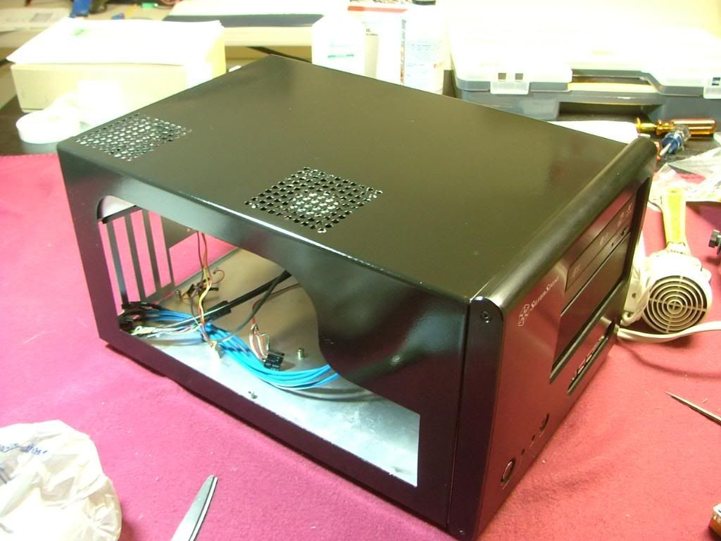
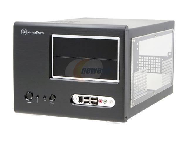
Here you have the factory windows for both sides (stock photos) which you can compare to views of the custom window above.
After much hem and hawing it was decided to keep DC as the bling water cooled system, but it changed positions with Kermit the Folder. Since the mobo/proc assembly has changed and it will be my primary SMP folder this will be DreamCatcher v3.5. Much thought went into this as originally it was slated to receive the Asus M3A78-CM / Kuma 7750BE. I felt that if DC v3.5s primary mission was to look pretty and be water cooled a tri-core would make more sense. Had thought of including the GTX 260-216 also but couldnt afford the water block. Here are the mechanicals:
CASE: SilverStone SOG1
PSU: Enermax Infiniti 650W
MOBO: Biostar Tf780G AM2+
CPU: AMD PI X3 8750BE
HSF: Cuplex XT di
GPU: Evga 8800GTS w/AquagraFX 8800
MEMORY: TWIN2X2048-8500C5DF
HDD: Seagate 7200.10 ST380815AS 80GB
Optical Drive 1: Soney NEC Optiarc AD-7200S
A lot of things occurred between v2.0 and the now v3.5, hopefully Ill present it in a meaningful manner. One of the reasons the MX6 case was dropped is primarily due to wanting a full coverage water block for the GPU. In the MX6 the PSU is directly above the vid card which precluded using the one I wanted. In the SG01 the PSU has been moved above the CPU giving me the extra room required.
February, 2009
The case was bought used and the prior owner cut a window in the side and apparently had a rad screwed to the top. These are his pictures and yes the dust was free!
Something the prior owner must not have taken in to consideration when doing the window is how little space there is between an interior window and the frame. Edging had been used to cover the cut, but if one was to attach a piece of plex for a window with the edging in place it would not have fit.
So I removed the edging and found a pretty good edge for the cutout. Where it was rough is in the bottom corners where the cooling holes are located. As you can see here .
I decided to square the corners as best I could and file the rough areas to be the finished edge and attach the window behind. I now know why the SOG1 factory windows are mounted on the outside.
Had a spare piece of plex lying around so decided to do an engineering sample of the window. One of the big things in putting in that window is Ive lost all of the lower cooling holes .especially those required by the hdd cage fan.
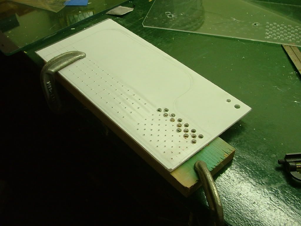
I taped the plex to the opposite side and scribed holes based on it hole pattern. My spacing and sizing will be different as Im afraid of cracking the plex if the holes are too close. Decided on multiple small holes in the hdd area with fewer large holes (3/8) for the rest. Here you see the rough layout with center punches prior to drilling. The centers are eye-balled so it wont be all that nice and neat!
You may wonder why I call the window an engineering sample, quit simple .
By experimenting on hole sizes and locations Ive saved a wee bit of heart break. You can see the material I have on hand is too brittle to drill. What I was able to do shows me the hole spacing is fine, but the pattern for the HDD fan needs to be lowered. Now to find some lexan to work with.
Needing to patch the holes in the top of the cover I drug out the stuff I used when doing the side panels of my original (unfinished and in the attic) Celtic Spirit.
It is easy to use and I just hope not too old! Backed the holes using painters tape with the hopes of only needing to sand one side. It turns out I mixed too little catalyst requiring about 2 2-1/2 times longer to cure. Then it was sanding time!! Also took the opportunity to smooth out as best I could the edges of the window opening.
Here we are ready for painting after it was done it appeared to be fairly reflective. I jokingly referred to the method as quick and dirty because of doing in a few hours what should be done over several days. However in the last pic youll see the patched holes .which if done with primer and sufficient coats of paint one shouldnt see. Lets just say this isnt one of my better paint jobs and needs to be located in a dark area of the office!
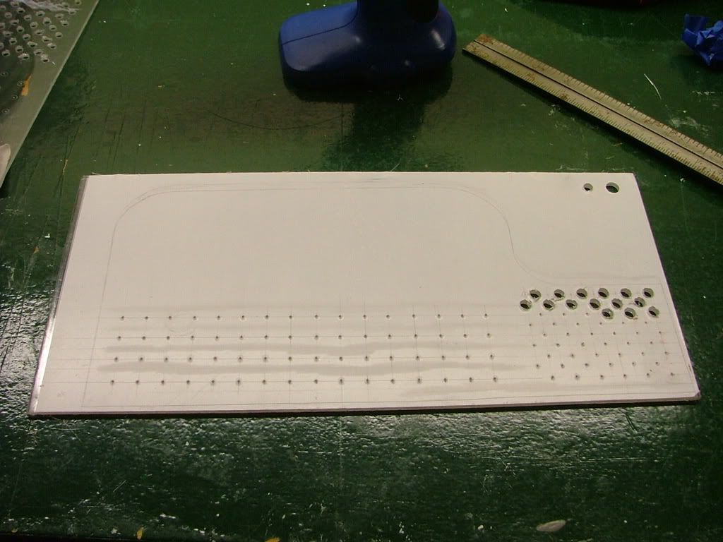
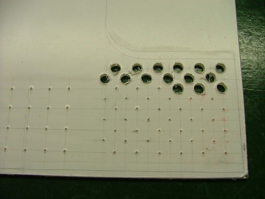
Finally got around to picking up a piece of Lexan for drill ability. The first few pictures I took are while laying out the hole patterns and beginning to drill. While it may appear somewhat inconsistent decided on two different size hole and patterns. You may notice the two stray holes up top that was a test in an area not seen. If you look closely youll see where the window edge is.
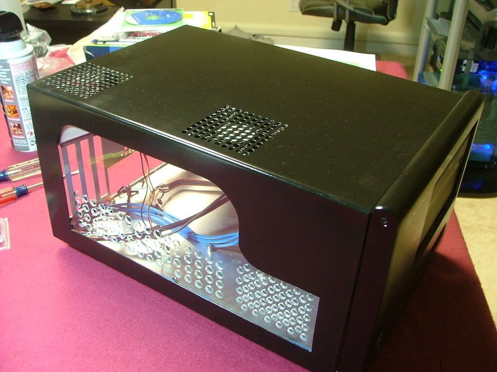
Lexan makes a big difference when it comes to drilling! It was easier by far over the plex but has it own minor issues. I was using a wireless drill at low speeds but it would still grab on occasions. Also I had difficulty in cleaning any rough edges and in the process managed to scratch the surface and will need to spend the time finding and using some glass polish. Here you have it temporarily mounted and in the closer views see some of the needed clean up.
As a safety valve I did manage to pick up a factory windowed cover as I wasnt sure how to do a window the right side. Wanted to have windows on both sides as the coolant is UV reactive and Ill be installing a pair of UV laser light fixtures. Also need to go back and do a little hammer, grind, and file to suit on the custom window as it is dragging on the frame and makes it difficult to install and remove the cover. Again I can certainly understand why the windows are mounted on the outside with the factory version.
Here you have the factory windows for both sides (stock photos) which you can compare to views of the custom window above.
Last edited: