Ok, i have a small Problem, well looking at the Gpu market right now, might be a big problem…
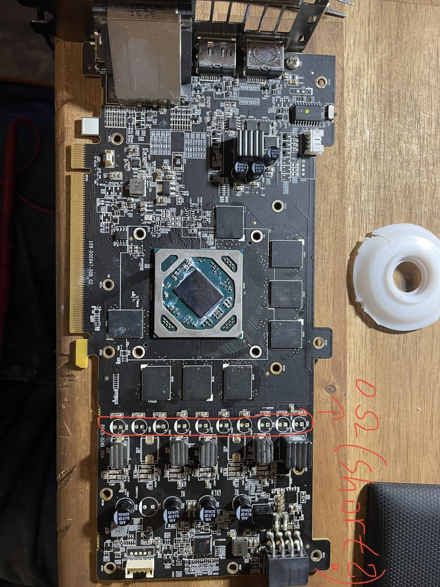
I jused an Rx 470 nitro+ 8Gb wich worked well, until it didn’t. One day the pc just wouldn’t recognize it anymore and fans won’t spin. Thought might be something defekt on the pin. First checkt the two fuses at the 8 pin and pcie fuse. Pcie worked, the other two were dead. Replaced it with similar 10A quick fuses. Before testing it again, I checked if the Mosfets were alright, through testing if Vin wasn’t connected with GND. Everything seemed alright. Tested the GPU, it worked. Few minutes later, PC crashed, same story again. Same fuses were dead and this time the Mosfets seemed to be shorted (Vin to GND). Since I didn’t knew wich one, a I detached all 4 and measured them. The dead one seemed to be open (connected) between gate, source and drain. I left it out, just to test the Card again without the short one and without replacing it. It worked again, for a few minutes. Now the two fuses near the 8 pin connector where alright. This time the Fuse near the pcie connector was dead. Also an other mosfet was shorted (the last one down on the Card). Somebody knows what’s going on? Why seems everything going to short after a while? Oh and before someone asks, yes i tried a different PSU actually a brand new bequiet 1200W. I have no more ideas what to do now?!
Picture of Gpu is below.
Edit: A second thought hit me. Is it possible, that the fuse near the pcie connector fries, because I startet the card without one of the Mosfets? So it tried to draw more power over pcie because the one MOSFET was missing? Also I assume, that the last mosfet on the card, is connected tonthenpcie connector instead of the 8 pin. That’s what I got from measuring them. If one gets shorted all but the last one are short to. But now, that the fuse near the pcie broke, this one MOSFET broke too.