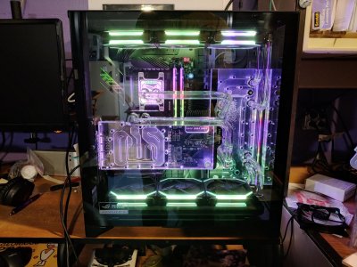
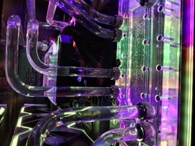
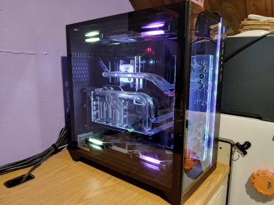
Project Black Glass

arnemetis

2[H]4U
Joined
Aug 2, 2004
Messages
4,086
Hello everyone!

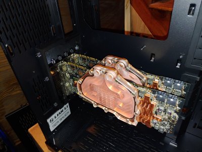
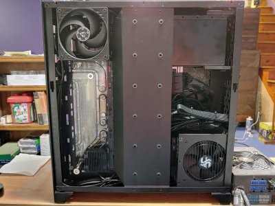
I am finally getting around to posting my worklog. It's been functional since July, but there is another significant mod I want to make. I learned a lot making this build, unique to me was having access to the full case 3d model from Lian Li, as well as a new 3d printer.

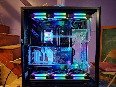
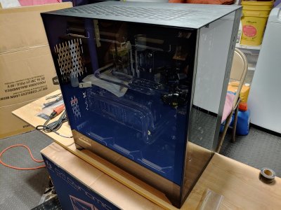
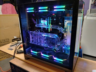
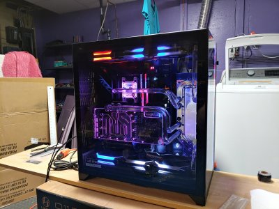
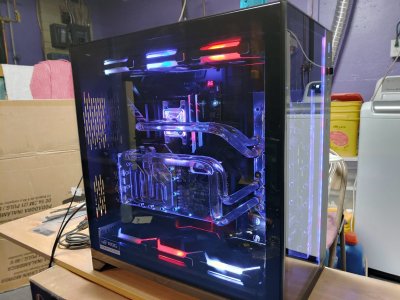
Thematically I wanted to try and make rgb look good, and not do a standard all black / red type case as I have done in the past. After deciding upon the Lian Li O11 Dynamic XL, I wanted to focus thematically on the contrast of transparency and darkness. This is where the name came from.

Enough intro, let's start things off with a parts list & photo of the good stuff!
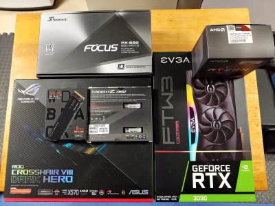
0609210053_HDR.jpg
Case: Lian Li O11 Dynamic XL (check this link if you're unfamiliar https://lian-li.com/product/pc-o11d-rog/)
Motherboard: Asus X570 Crosshair VIII Dark Hero
CPU: AMD Ryzen 5950x
RAM: G.SKILL Trident Z Neo 2x16GB F4-3800C14D-32GTZN 3,800 Mhz / 14-16-16-36
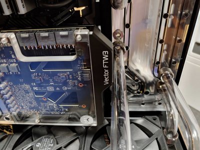
GPU: EVGA GeForce RTX 3090 FTW3 ULTRA GAMING 24G-P5-3987-KR
PSU: Seasonic FOCUS PX-850 80+ Platinum
PSU Extensions: LINKUP 30cm Braided w/Comb Kit ┃1 x 24 P (20+4)┃2 x 8 P (4+4) CPU┃3 x 8 P (6+2) GPU Set┃300mm Black
SSD (Primary): WD Black SN850 PCIe NVMe 4.0 2TB
SSD (Secondary): Inland Premium PCIe NVMe 3.0 1TB
Fiber NIC: Mellanox MCX311A-XCAT CX311A ConnectX-3 10GbE SFP+
PCIe risers: LINKUP PCIe 4.0 X16 90 Degree Socket 15cm, LINKUP PCIE 3.0 16x Straight Socket 10 cm
USB hub: Sabrent 5 Port Internal USB 3.0 Hub Controller HB-INTR

Cooling components:
Radiator fans: Lian Li Uni Fan SL120 Black x6
Case fan: Arctic P12 PWM PST
Reservoir: Lian Li O11D Distribution Plate G1 by EK
Pump: Swiftech MCP35X 12V DC Pump with EK-DDC Heatsink Housing Black
Radiators: Hardware Labs Black Ice Nemesis 360GTS x2
CPU Block: EK-Quantum Magnitude D-RGB AM4 Nickel + Plexi
GPU Block: EK-Quantum Vector FTW3 RTX 3080/3090 D-RGB Nickel + Plexi with EK-Quantum Vector FTW3 RTX 3080/3090 Backplate Black
Fittings: Bitspower G1/4" Black Sparkle Advanced Multi-Link For OD 16MM x16, Bitspower G 1/4" Temperature Sensor Plug Black Sparkle, Bitspower G 1/4" Mini Valve Matte Black
Tubing: EK-HD PETG Tube 12/16mm
Coolant: EK-CryoFuel Clear
 
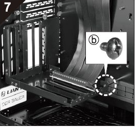
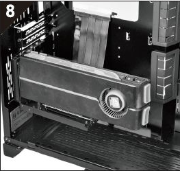
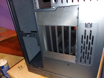
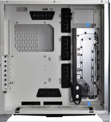
Right out the gate I was interested in exploring vertically mounting the gpu. Always hated not seeing my gpu water blocks. However I really did not like Lian Li's bracket, which results in the gpu being set into the case, and a big hole left in the back for you to pass your displayport & hdmi through:
1636868996001.png
1636869288470.png

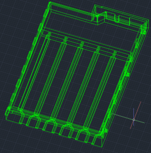
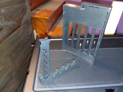
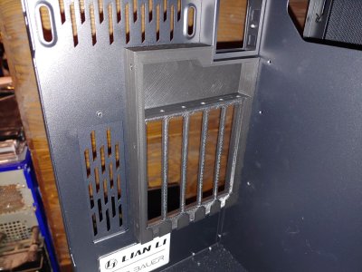
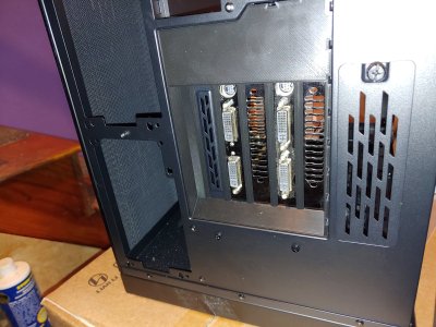
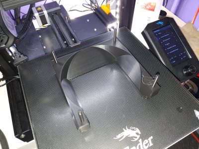
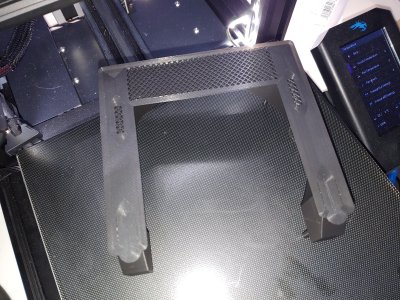
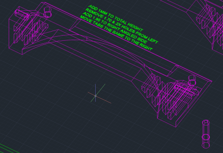
It also just looks really janky and unclean, so I decided to start designing my own rear pci bracket. Thanks to Lian Li providing the stp file, I was able to import the entire 3d model into AutoCAD to start my work. Thankfully the actual case is quite close to the 3d model in size, so I only needed one test piece to get my first prototype in place:
1636869373644.png0221211452_HDR.jpg0222211836.jpg0225210004.jpg0225210003.jpg
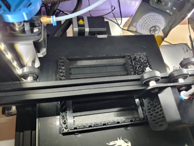
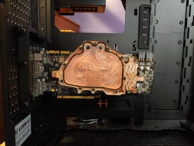
With some effort and fighting (I may have made the tolerances a bit too tight,) I was able to snap it into place, and I was pretty happy with the result! The holes at the top would be threaded by the thumbscrews with some elbow grease, and the bottom grooves to capture the brackets just needed a little cleaning from the 3d print process. This also plugged up some of the open gaps in the original layout. So next I wanted to do some mock ups, to see if my prints were strong enough to actually use, and to see how it would come together. My old gtx 260s were volunteered for this job.
0225210023.jpg0225210024.jpg0225210016.jpg
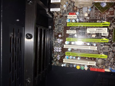
Looking pretty good! I didn't plan on going sli, but I figured I would give it some extra weight for the test. I then got worried I had made the bracket too large, and it would interfere with the motherboard. So that needed a test fit as well. My old evga 790i ftw motherboard came out of storage for service.
0225210036.jpg
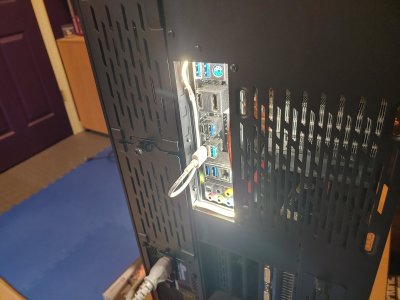
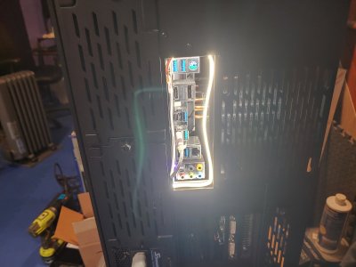
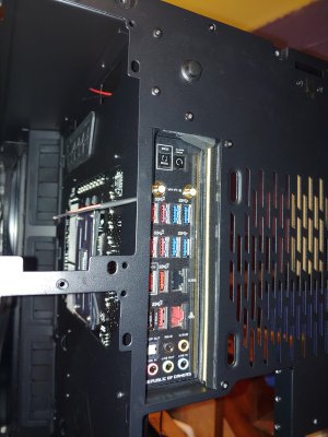
Finally for this section, I was playing with the idea of lighting up the io part of the motherboard, to make life easier when plugging devices in. Especially with VR, this is something that annoyed me with my previous build so I did a quick mockup to get the ideas flowing.
0321211942_HDR.jpg0321211943_HDR.jpg
 
  • Like
Reactions: Nobu
like this
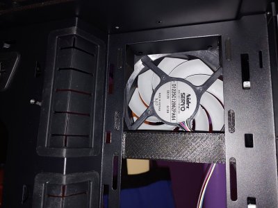
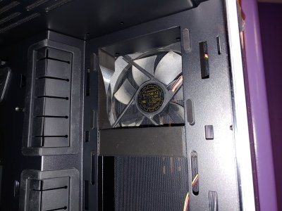
Next my attention turns to the distro block. This would be my first time going with one, as well as my first time trying hard line tubing. Someone had made a 3d model of the block, so I brought it into cad and started playing with positioning it. With the XL case, it cane be adjusted up or down by a good bit, leaving some dead space. I thought this might be an opportunity to make use of that space to bring in some extra air and establish positive pressure. Here's a shot that shows unused space above the distro plate:
1636870754891.png

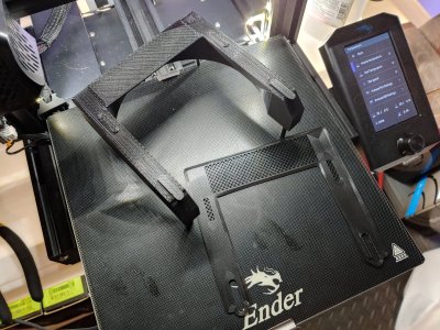
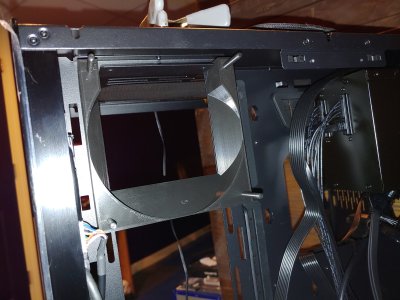
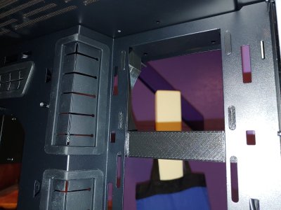
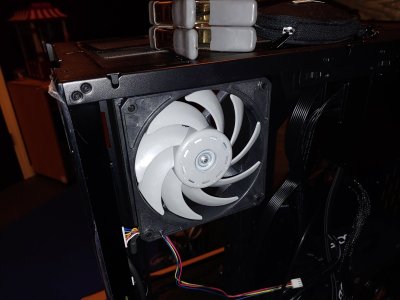
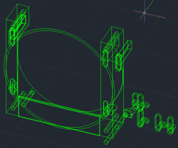
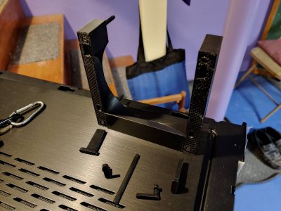
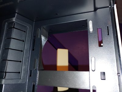
Since the ports are closer to the top than the bottom, I decided on keeping the distro block low as shown here. I got to work designing a support piece & shroud for another 120mm fan. I didn't take cad shots during this time, so all I can show are the 3d printed parts. This design depended on printing oval tabs to match the cutouts in the case, which I would slide into place and they would be press fit and rely on gravity to keep it from moving. The four posts would hold the fan, depending on standard hole locations. It would be pressed against the mesh filder o nthe side panel of the case, so it wouldn't wobble around or come loose.
0420211236.jpg0420211237.jpg0420211243_HDR.jpg0420211252.jpg0420211252b.jpg0420211258.jpg0420211258a.jpg
This was ok, but there were several problems. The press to fit was again too tight of a tolerance, and it didn't really sit flat against the case as I had hoped. The posts to hold the fan were weak, and one broke off quickly while testing different fans. This was a lesson I was learning with 3d printing, layer direction matters. This orientation of course made it all too easy to snap them off. So I moved away from a single piece and made a system of pins and tabs to hold everything in place, and ensure structural integrity of the 3d printed parts.
1636871973528.png0427211301_HDR.jpg0427211303a.jpg0427211306.jpg
While far more complex, this system works well. The pins push through and hold the fan just fine, they were printed laying down so the layers lines are along its length and they will not snap. The bottom slots have an extra area cut out, so that they can turn 90 degrees and lock the bottom in place. The top tabs are press fit, and are able to be adjusted to alight the shroud vertically. If the distro plate for example ends up too high or too low, I can print the tabs again after adjusting the rectangular section of the tabs up or down. The inside lip of the over portion locks it in place.
 
  • Like
Reactions: Nobu
like this
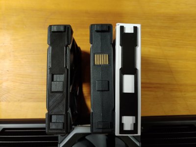
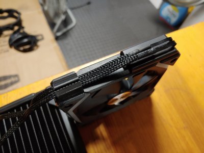
Next I started putting more pieces in to see how they fit, and I noticed a few issues with my fans and the radiators. First is that the spacing of the holes on the radiators was slightly off, so I could not secure all the fans with screws. This meant in the end I only screwed in the center fan of each chain, but since they are mechanically locked together that is ok. So the SL120 fans can link to each other to also minimize cables and to synchronize the rgb easily, but this means on one end there will be exposed metal contacts. I designed a simple cover that I was immediately happy with. I also made some clips to guide the cables since the orientation of the connector had the cables facing the wrong way.
0515211145.jpg0515211148.jpg0516211431.jpg
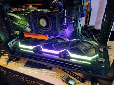
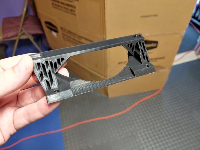
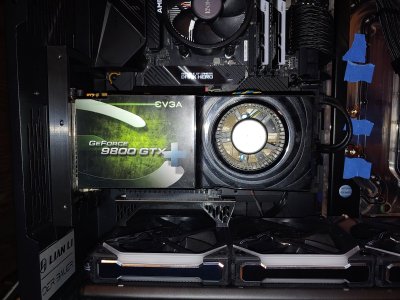
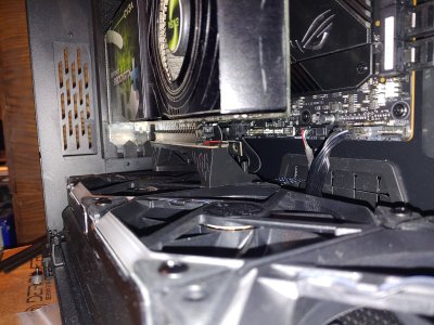
Next I had begun connecting more components and I swapped in a 9800 gtx+ because I needed a gpu that actually functioned to boot the system (the 3090 would not be secured for a few more weeks.) This also allowed me to start developing the bottom support for the gpu, which I needed more on the fly measurements of due to the complexities of components. I made some orange blocks to find the exact height needed to support the gpu properly.
0515211223_HDR.jpg0512211215_HDR.jpg0528212328_HDR.jpg
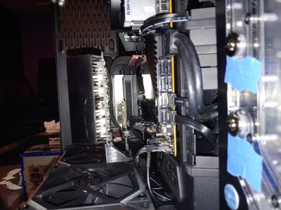
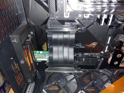
After confirming the 3090 sat at the same height as the 9800 gtx+, I went back to using that gpu for my mock ups, and began working on a properly designed bracket. I got more detailed with this piece, and tried to utilize a parallelogram hole design like the rest of the case has, while also making it something that could be 3d printed. I also wanted to ensure the riser cable for the fiber card would clear the bracket. I went through several prototypes, making adjustments until it fit just right.
1636876475651.png0531211818_HDR.jpg0531211813.jpg0531211814.jpg0531211814a.jpg
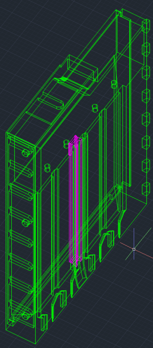
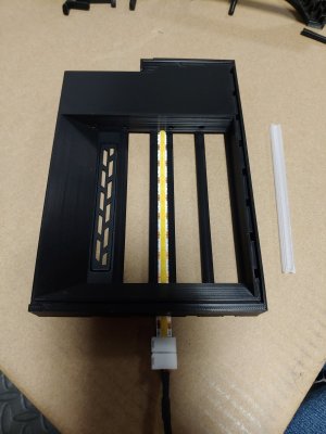
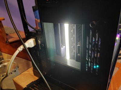
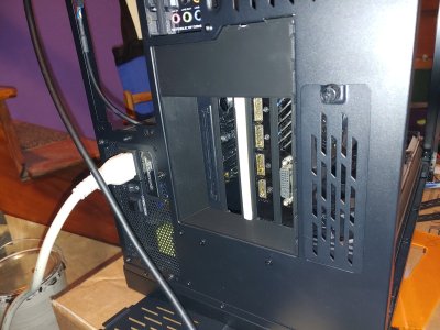
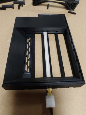
At this point I had also revisited the design for the pci bracket, thinking about how I could incorporate lighting here as well as at the motherboard io. I originally designed a little clip to run an led strip along the empty pci cover, but that didn't work too well. I decided to try reducing the number of available slots to 4, and added a space in the middle to allow an led strip to run in the center of the bracket. By making a diffuser out of clear PETG on the printer, I was able to get bright but not blinding light to illuminate the pci area. I also took this opportunity to refine the fit a little more on the bracket.
1636877161754.png0610210125.jpg0610210126.jpg0601211721_HDR.jpg0601211721.jpg
 
  • Like
Reactions: Nobu
like this
that LED strip is a great idea. Would be cool if manufacturers integrated that into an integreated IO shield sort of how sometimes they light up the clear part of the mobo pcb around audio isolation.
 
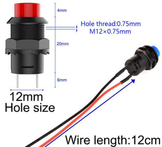
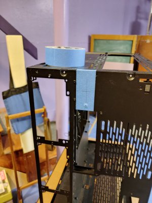
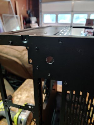
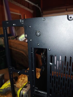
After getting the led lighting design down for the pci bracket, I next had to think of functionality. I figured a button would be simple enough, and since I planned on powering this via usb I didn't need much. I found some simple on / off rocker buttons on amazon, and decided to mount this at the top of the rear of the case. The hole would be cut easily with a step bit. The wiring would be mostly hidden with the upper radiator anyway. Even though I bought a multi pack, of course I had to use the black button.
1636949746985.png0607210257_HDR.jpg0608211523_HDR.jpg0608211524.jpg
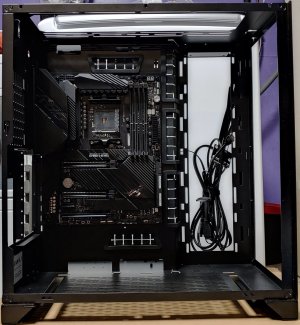
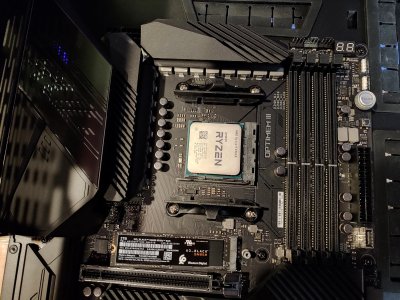
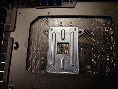
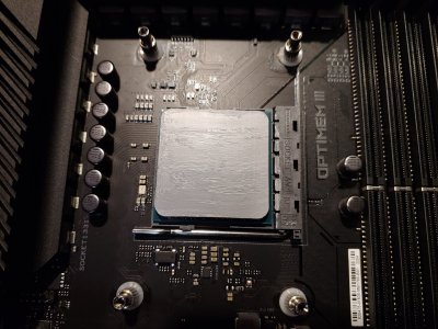
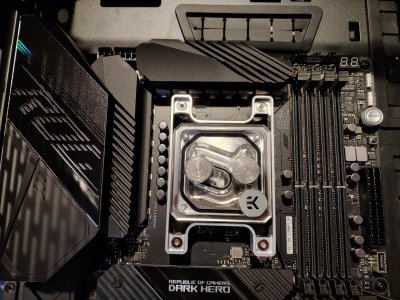
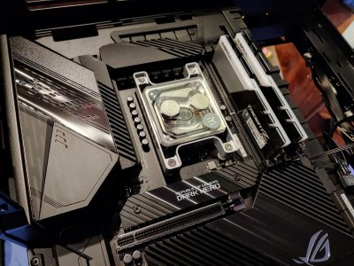
It was time to start assembling parts in their final place, starting with the motherboard and cpu. I think the motherboard by itself in the case looked quite nice. Too bad I will be hiding half of it. For the CPU I used the Thermal Grizzly Hydronaut that came with the cpu water block. Last image here I tried to get a slick shot with the ram installed.
0609212322_HDR.jpg0609212333_HDR.jpg0609212348_HDR.jpg0610210007.jpg0610210016_HDR.jpg0610210023_HDR.jpg
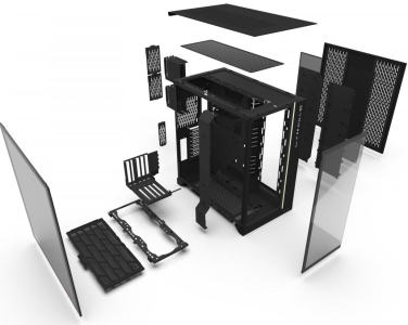
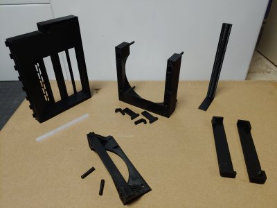
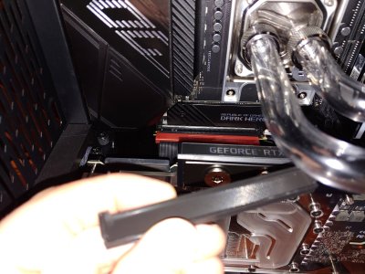
Now it's time to put all the 3d printed parts back in, so I took the opportunity to snap a photo of all of them at once. A few new additions here would be the led strip frame for the motherboard io area shown in the top right, thankfully the 3d print was flexible enough to bend it while fitting it into place, and I made sure it was smaller than the overlap of the rear metal so it looks clean. On the bottom right are two plugs that cover some open areas that bypass the air filter due to the way Lian Li designed the filter's frame. The use of these plugs forces all the incoming air to go through the filter instead. I will include a reference exploded view so you can see these two rectangular cutouts at the bottom of the case (they exist because this is how they formed the support for the bottom filter.) I also gave the wiring a test to make sure it functioned correctly off of usb power.
1636951369289.png0610210059.jpg0610210109.jpg0612210110_HDR.jpg
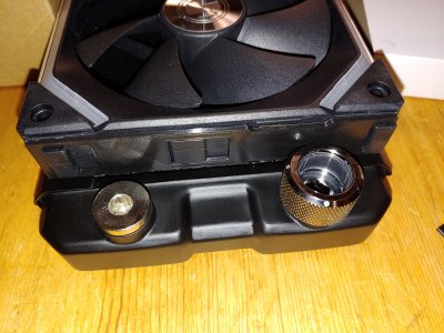
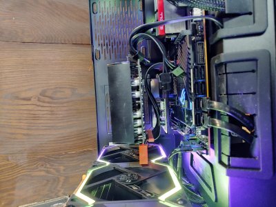
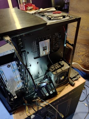
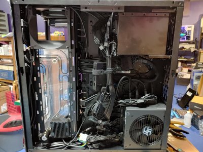
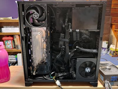
Now it was time to run most of the electrical. Access to the bottom half of the motherboard would be cut off once the gpu was in place, so that had to all be wired in first. I also figured all the other psu wiring should be dine now while I had access to an open case. I got it mostly done, knowing I would have to tidy things up a bit more once the gpu power was connected. The extenders ended up being a fairly large waste of space, on the back side anyway. The usb hub was magnetic, so I stuck it to the psu since that area was otherwise unused. I needed the hub because this case has two usb 3.0 headers, but most motherboards only include one. Also you can see I put some heat shrink on the pump cables, and the valve which does clear the back panel & filter.
0613211624_HDR.jpg0615211055_HDR.jpg0615211810.jpg
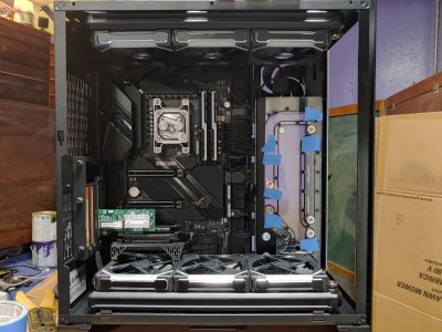
It's starting to come together. The green fiber card is an eye sore, but it will be impossible to see from any angle when complete. The top radiator is installed here along with upper fans, like below only the center fan is screwed in. Both nvme drives are installed now, especially the secondary one on the bottom will be inaccessible. The upper slot with the primary drive might technically be accessible, hopefully I won't have to replace these drives anytime soon.
 
  • Like
Reactions: Nobu
like this
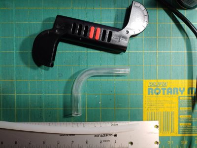
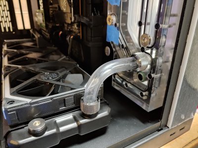
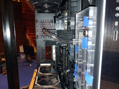
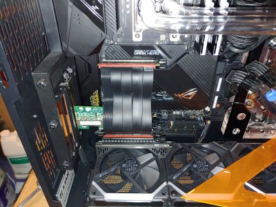
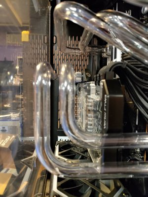
Finally the part I was looking forward to and also terrified of, the tube bending! I had a basic Wagner heat gun from Lowes so I used that, some lightly soapy water, a simple bending tool, and a silicon insert. I watched some videos to try and get an idea of how to do it, my biggest takeaway was to go slow and be sure to actually heat up the tubing long enough & far enough on either side of the bend to avoid stretching. I also learned that PETG tubing is pretty easy to scratch, so keep your work area clean! First attempt I decided would be a single bend. I cut all my pieces with a standard plumbing pipe cutter that I cleaned up since it had been used a lot on copper and was leaving marks on the PETG. I also have a pipe reamer to clean the inside & outside edges of the sections.
0616210040.jpg0616210115_HDR.jpg
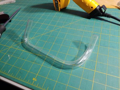
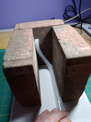
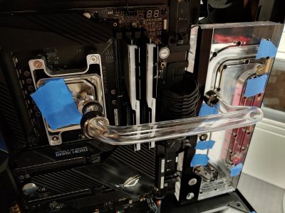
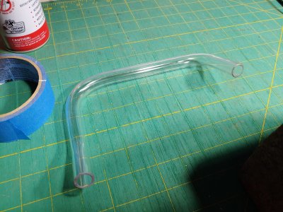
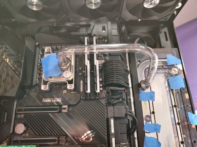
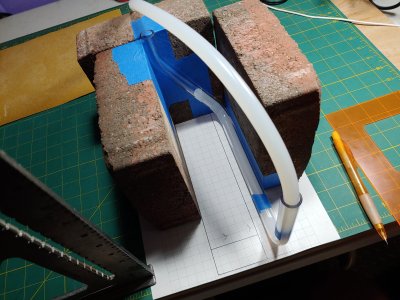
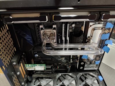
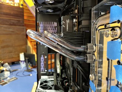
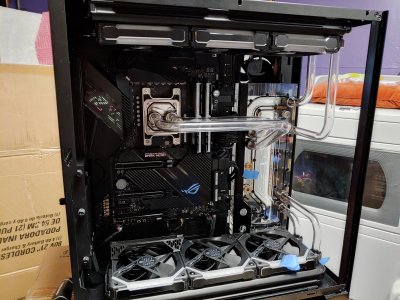
A good start, but I needed to make it a bit tighter. Where it connects at the radiator, it was still curving so the fitting scratched up the tubing forcing it into place. Next up I dove head first into an empty deep end, doing a three bend section to the cpu block. I wanted my runs to be highly angular and in line with each other, and because I hate myself I didn't want to use any 90 degree fittings. I grabbed some patio bricks from the backyard and used some grid paper I printed out with measurements I took to try and size this correctly. This had to go far enough out that I could still remove my ram. I learned a whole lot with this first big piece.
0617210136.jpg0620211848.jpg0620212008_HDR.jpg0622210151.jpg0622210153_HDR.jpg0622210154.jpg
It took probably 6+ hours over several days and attempts to get this piece to come out as you see above. The first one ended up being discarded because you can only redo the same bend about three times before the whole section starts to deform unpredictably. After this piece however, my confidence went way up and I dug right into the companion cpu run, which went faster and I think looked better than the first run. I also put painters tape on the patio bricks to stop damaging the PETG so much. I spent only a small amount of time fine tuning the bend so the angled section was parallel, I was pretty close on my first pass.
0624210239_HDR.jpg0624210240_HDR.jpg0625210047.jpg0625210134_HDR.jpg0625210134a_HDR.jpg
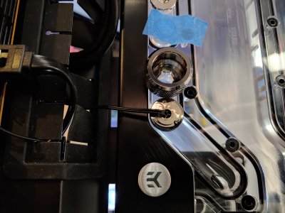
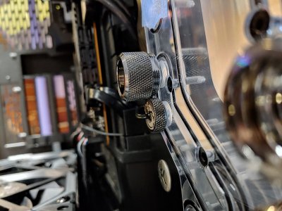
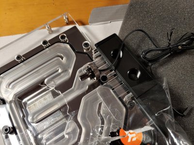
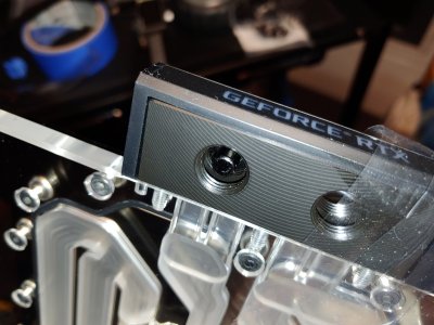
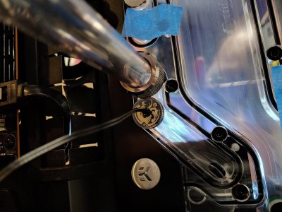
Moving on to the lower ports for the gpu run, I started by doing what I did before - fit some straight sections and make measurements so I start a lot closer to the end dimensions. This showed a slight problem with my plans however, as the fitting would not screw in with my temperature sensor screwed in.
0626210148a_HDR.jpg0626210149_HDR.jpg
Well that won't work. My options are rather limited, perhaps the back of the gpu power? No I don't think that would work, it looks like will block too much flow.
0626211259_HDR.jpg0626211255.jpg
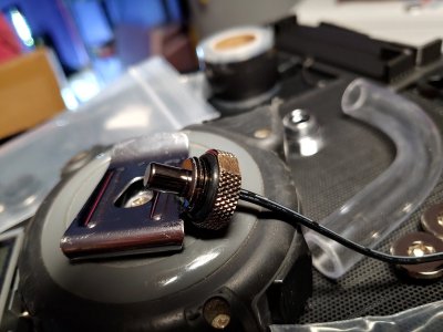
Ok well then, it's time to mod the temperature sensor. I figured there was no way I would damage the sensor in the middle of the fitting if I just trim it back a bit. Dremel to the rescue!
0626211410_HDR.jpg0626211406a_HDR.jpg0626211406_HDR.jpg
Let's wrap it up tonight back on the tubing. I decided to make the four single bend sections for the radiators next. This would finalize the radiator positions, thankfully the case uses slots instead of holes for the radiator screw locations. Starting to look pretty interesting now, a lot more of that transparency component.
0627210257_HDR.jpg0627210258_HDR.jpg
 
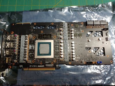
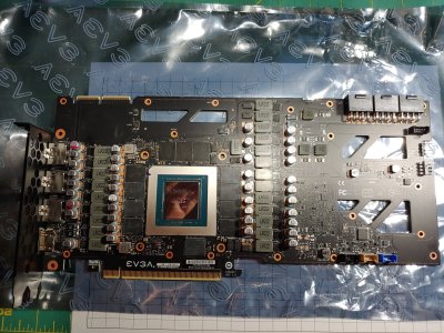
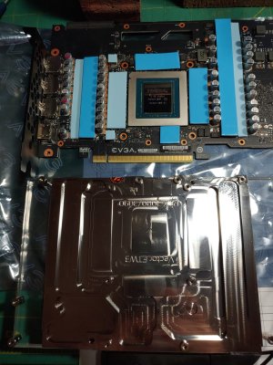
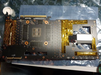
Alright it's time to start ripping the gpu open for cleaning & water block application! The putty took for freaking ever to clean out, it's really gummy stuff.
0627211009.jpg0627211119.jpg0627211138_HDR.jpg
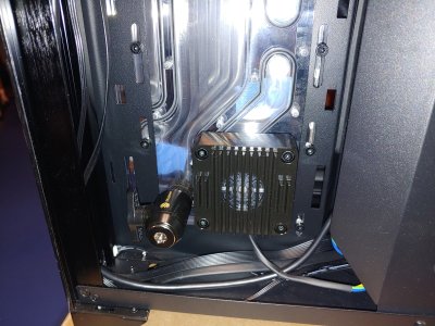
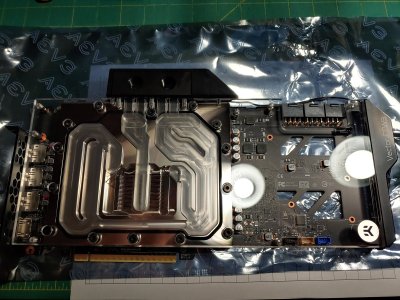
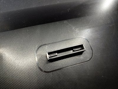
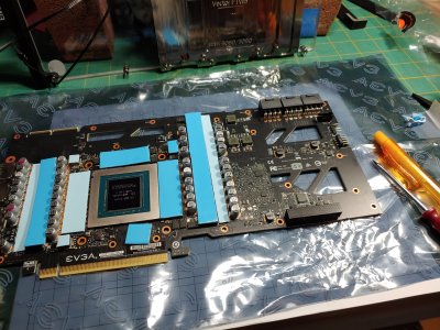
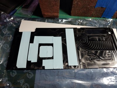
So with a mock up of the block, I see the three headers for the default fans stand out pretty bad. So I made a simple 3d printed cap to mask them. Then I started laying out the thermal pads.
0627211305_HDR.jpg0627211335.jpg0627211644.jpg
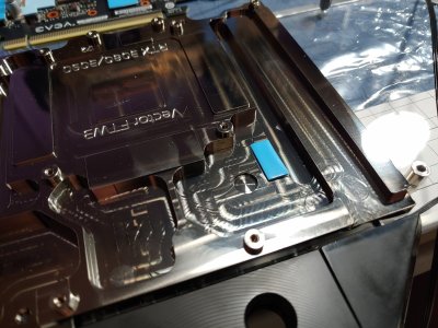
If you notice the last image there, we have an issue. I took the pad off the LR22 component here to show that the area of the block is raised - no contact would be made with a thermal pad! Now looking back at the image with the putty and pad residue on it, you can see the stock cooler does not make contact with it. However the instructions with the EK block do call for a pad there. Well there are plenty of extra pad pieces, so maybe I can stack a few...
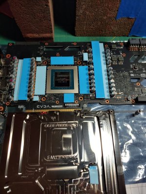
0627211649.jpg0627211710_HDR.jpg0627211723.jpg
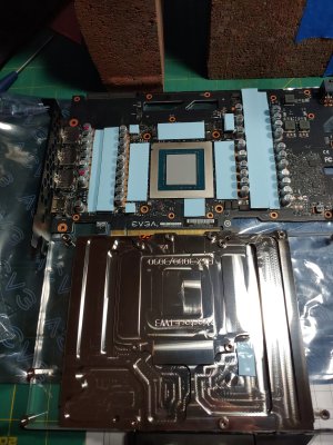
Above you can see the gpu side prepared, including the paste on the core that came with the block, EK-TIM Ectotherm. Next we see the back side, where I used some Kapton tape to protect any metal protrusions from contacting the back plate, as suggested by a post here on the forums. Others had experienced issues with the EK block, and it seems the back plate sits closer than the evga one so a little flex could cause shorts.
0627211047.jpg0627211846.jpg0627211854_HDR.jpg
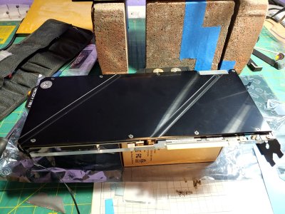
Let's do a test fit and see how it looks! Things are pretty close.
0627211914_HDR.jpg0627211922_HDR.jpg
Let's wrap this post up with the light testing I did, to make sure all the electrical connections were in place before I start doing final plumbing, which marks the point of not being able to reach behind the motherboard anymore.
0627211936_HDR.jpg0627211940_HDR.jpg
 
So before I got going with the gpu plumbing, I noticed something else that was out of place. The pcie riser cables have red plastic at the ends, and it really stood out. So I made some 3d printed caps like I did for the gpu fan headers, they fit snugly and are just a friction fit.
0630211200.jpg0630211258.jpg0630211445.jpg
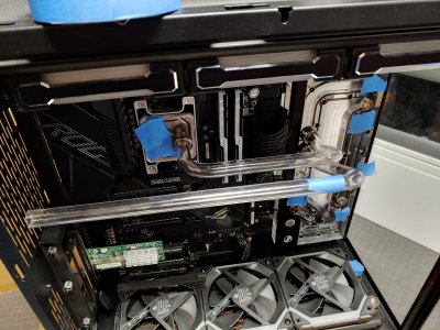
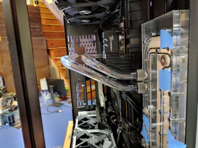
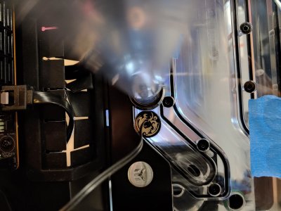
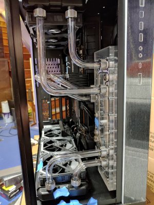
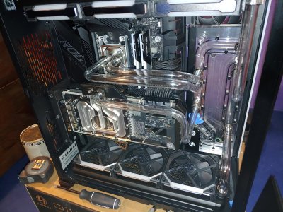
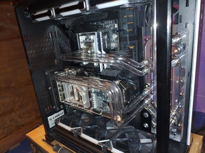
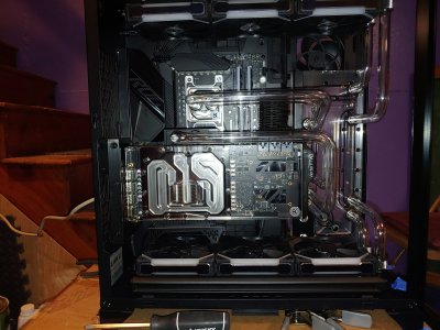
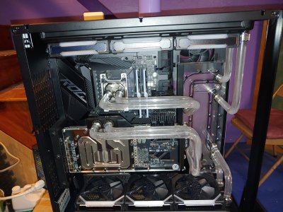
Ok let's get on with it. Since these two tubes would be the closest to the glass, I had to be very careful with the bends to make sure I clear everything. I didn't take much for photos on the way this time, I know for example the last tube took 5 hours straight of me carefully measuring, bending, and adjusting. In the end there's like 1/8" gap between the glass and the last tube run.
0703210421.jpg0703211803.jpg0703211803a.jpg0703211807_HDR.jpg
Time to fill the loop and start the leak test! Filling from the back side through the upper most port into the reservoir, ended up with tons of bubbles because the pump struggled to fill up the first gpu line. I also need to put some work into cable management while that starts working.
0703211851.jpg0704210053_HDR.jpg0704210019_HDR.jpg0704211231_HDR.jpg
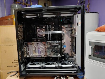
The test completed without issue! I got windows installed and confirmed everything was detected correctly, and got the L-Connect software installed to see what was up with the fans. Since I got it running on the 4th of July, I tried to do a red white and blue theme for the day.
0704211248_HDR.jpg0704211338_HDR.jpg0704211455_HDR.jpg0706211006_HDR.jpg
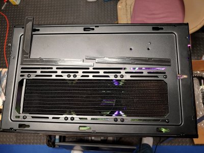
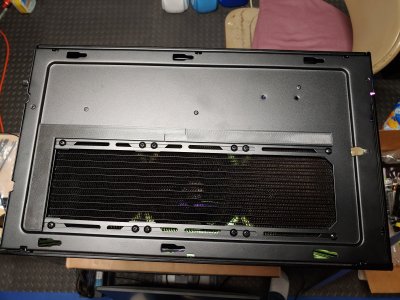
I started leaning toward a yellow and purple combination for lighting, which I would continue tweaking for a while. After a few days of operation I observed another opportunity for me to 3d print a fix to a problem. The top of the case is set up to support 3x120mm or 2x140mm. This means there is a lot of extra space that is open without resistance like at the radiator, so I wanted to prevent debris from falling in. Due to the size I had to print two pieces and snap them into place.
0708211112_HDR.jpg0708211113.jpg
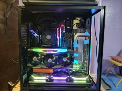
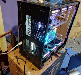
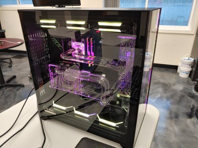
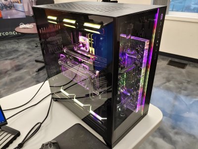
Let's wrap this post up with the end of the photos, a few shots when I brought it into work and then some more shots I took that I thought looked nice.
0709211138_HDR.jpg0709211139_HDR.jpg0713211723_HDR.jpg0723211302_HDR.jpg
 
Last update for the night, to show how the setup is working for me right now. Found a happy place with the yellow & purple. I also have some videos I took along the way, sorry for the potato quality. I expected better out of my LG V40, but I suppose the lighting down here is garbage.
1122210010a_HDR.jpg
 
Back
Top