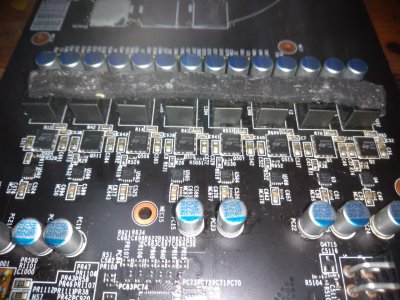
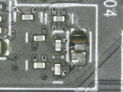
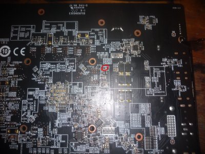
MSI RX 580 GAMING X+ 8GB Repair

Joined
Nov 4, 2010
Messages
24
trying to repair an rx580 there are no shorts on any of the rails and all resistances are normal all voltages are present except vcore
dont know where to start with this one anyone know where to begin
 
Last edited:
Its uses GS7256 for memory and memory controller
http://www.gstekic.com/pdf/GS7256.pdf

These are the voltages i got from memory controller (one on front of board)
Pin 1 = 10.32
Pin 2 = 1.33
Pin 3 = 0.34
Pin 4 = 9.65
Pin 5 = 11.92
Pin 6 = 0.60
Pin 7 = 1.17
Pin 8 = 0.76

These are the voltages i got from memory
Pin 1 = 9.2
Pin 2 = 9.25
Pin 3 = 1.95
Pin 4 = 8.84
Pin 5 = 11.98
Pin 6 = 0.60
Pin 7 = 1.24
Pin 8 = 1.06

Its Dropout Linear Regulator Is GS7166
http://www.datasheet-pdf.com/PDF/GS7166-Datasheet-GStek-1095896

These are the voltages i got from it
Pin 1 = 3.3
Pin 2 = 3.3
Pin 3 = 3.3
Pin 4 = 5.0
Pin 5 = 0.0
Pin 6 = 1.8
Pin 7 = 0.68
Pin 8 = 0.0

QM3816N6 Mosfet

https://pdf1.alldatasheetde.com/datasheet-pdf/view/1116495/UPI/QM3816N6.html

8510
https://datasheetspdf.com/pdf/920061/CHiLSemiconductor/CHL8510/1

These are the voltages i got from it
Boot Pin 1 = 12v
VCC Pin 4 = 12v

Multi-Phase Controller It uses is ir35201
http://www.irf.com/product-info/datasheets/data/pb-ir35201.pdf

These are the voltages i got from it
Enable Pin 21 = 3.3
VCC Pin 38 = 3.3
Dont know if anything else is need from that chip
 
Last edited:
thumbnail_IMG_20220103_131715838.jpg

think im nearing the problem Should the resistors R528,R29 and so on all be the same value?

R528 = 8.7k
R29 = 5.2k
R529 = 8.5k
R28 = 0.00
R530 = 8.7k
R652 = 8.5k
R38 = 8.7k
R78 = 8.7k
 
Last edited:
I'm not likely much help, but resistors are not easy to kill. If any of the resistors was bad it would be visibly exploded or burned.
Don't go changing resistors. Would be my advice.

How do you know the voltages are all correct? Where does the vcore come from? I would trace that as far as you can.
 
never mind about the resistors my meter was giving different readings every time i measured just turned it off and on again seems to be ok now
measured them again they are all the around the same must be something else
 
Typically it's another MOSFET, but a low voltage low power MOSFET connected to a switching circuit that provides the gate voltage.

It's almost always the high power MOSFET that fails.....
 
i dont think its the mosfets,
did some more voltage tests and all of them have no voltage at the gate pin only 12v at drain pin is present
 
There are MOSFETs that conduct when the gate is tied to ground.

How are you testing the MOSFETs?
 
forgot they were dual mosfets, only tested high side
all of them are showing a short from drain to source on low side
 
Which rail are we talking about here? The main core power? What resistance in ohms, not just "not a short" do you have from the output side of the inductors to ground?
 
12v is there just not the vcore after mosfets
resistance on two inductors under 8 pins is 1.4k and rising no short in diode mode
resistance on gate of high mosfet are all around 8.7k
resistance on gate of low side are all around 1.8k
 
12v is there just not the vcore after mosfets
resistance on two inductors under 8 pins is 1.4k and rising no short in diode mode
resistance on gate of high mosfet are all around 8.7k
resistance on gate of low side are all around 1.8k
What resistance do you have at the output side of the buck converter inductors?
 
The two capacitors of the same size just below it are probably the same value. You'll have to remove one of them from the board to measure it, you can't measure it in circuit. Just be careful when removing it, MLCC caps are very fragile, if it cracks, it's done and needs to be replaced as well.
 
Back
Top