Motherboard trace damage, repairable?

Lothar582

n00b
Joined
Aug 15, 2022
Messages
9
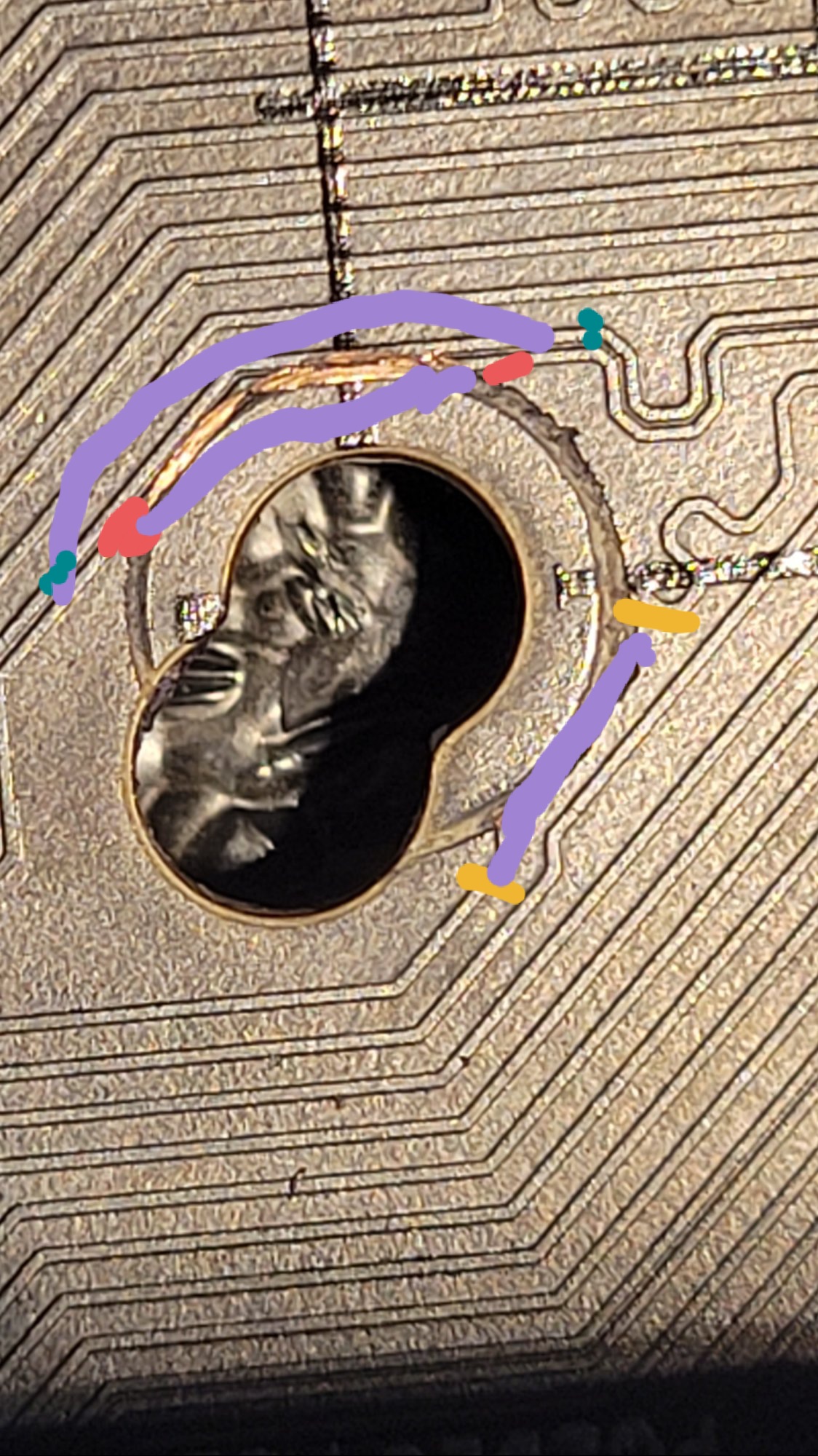
I have a motherboard with some damage around the mounting points for the cpu cooler. Looks to have dug into the PCB and caused damage to the traces. Will only post with ram in B1 or B2 Dimm slots.
Is this repairable? Should I bother, or would it be a waste of my time looking for someone to fix it?

20220813-175851.jpg
 
So you do not think this is repairable? I have 2 sticks and it would be unfortunate to lose dual channel performance.
I dont think it is easily repairable. Everytime I lost a memory slot or channel on a motherboard (normally due to bent CPU pins not damaged traces) I just delt with the limited ram. I think I went from quad channel to dual channel ddr3.
 
I've seen older mobos with larger traces be "easily" repaired. I say easily because the skill of the tech probably made it look easy. When traces get tiny and length critical, like memory or CPU traces, it can be trickier and doesn't even look easy or fun. Although fun is subjective.

That said, wouldn't hurt to email a few repair places, if only to ease the decision to let go of the board on ebay for a parts or not working price.
 
You probably aren't going to find anyone who would want to even bother. If someone can do it I doubt it would be cost effective versus replacing the motherboard.
 
There are the YouTubers that do repairs like this one of them might be interested in trying for a video. Tronicsfix is one.
 
What cooler were you using ?...........A properly insulated cooler bracket or water block wouldn't dig into the board like that or cause a short when making contact. If the traces aren't cut you could put some clear nail polish on them. Make sure whatever cooling system you are using has an insulated bracket or plastic stand-offs like Noctua. Also meant to ask if there's any damage to the back of the board.
 
Last edited:
Is the trace actually cut or is the soldermask (black coating) just scraped off? If the copper is intact just recoat it with some nail polish and when you mount it again use a nylon or paper washer over top to protect it
 
Don't waste your time. Buy a new board and be done with it. Be careful with your HSF mounting the next time.
 
There are the YouTubers that do repairs like this one of them might be interested in trying for a video. Tronicsfix is one.
I didn't even consider that at all. Ill do a seqrch for some youtubers that do that. It's certainly worth a try.


You probably aren't going to find anyone who would want to even bother. If someone can do it I doubt it would be cost effective versus replacing the motherboard.
This is kind of what I was thinking, just wanted some input from you guys on the forum. And I was really hoping to get it to work since I'm working on a very low budget, and I didn't pay much for the board.

What cooler were you using ?...........A properly insulated cooler bracket or water block wouldn't dig into the board like that or cause a short when making contact. If the traces aren't cut you could put some clear nail polish on them. Make sure whatever cooling system you are using has an insulated bracket or plastic stand-offs like Noctua. Also meant to ask if there's any damage to the back of the board.

Im not sure what kind of cooler was attached, but after considering the damaged locations I think it might have been a stock Intel LGA1700 heatsink. Kind of matches the profile of the legs which rest against the PCB. Although, Intel would never design a cooler that could do something like that, right guys? 😆

Also, why are there even traces located on the mounting points, and if there are there, then why isn't there a protective ring around the holes like there are for every screw location on the motherboard mounting points. I dunno, in a properly designed board, damaging motherboard traces by overtightening a cpu cooler should not even be a thing imo.

Is the trace actually cut or is the soldermask (black coating) just scraped off? If the copper is intact just recoat it with some nail polish and when you mount it again use a nylon or paper washer over top to protect it
I'm not 100% sure if the traces are cut. I think they may be in one spot where the gash is somewhat dug into the board.

Just cleaning the area thoroughly with rubbing alcohol and coating over with nail polish didn't produce any reaults.

I've been doing a little research on damaged teaces so today I'm going to try and scrape delicately with a needle between the traces first in case there is a short between them, and I'll try recoating again. One of those magnifying scopes for electronic work would prove real useful right about now lol.

I'll post some better quality pics later and update on how it turns out.

Again, thanks to everyone here who posted comments. I appreciate ya.
 
delicately with a needle between the traces first in case there is a short between them, and I'll try recoating again
try that and if you happen to find any breaks a lead pencil might work to fill it in, like unlocking the old durons/athlons....
 
If the damage is limited to just a couple of traces like the photo shows, it probably is possible to repair this. You'd need some real fine wire, an exacto knife, a soldering iron (a powerful one with a real fine tip) and a very steady hand. A microscope would be immensely helpful. Once you had the traces repaired, you'd probably want to add some conformal coating, and your choice of heatsink would then be dicated by which types present the risk of damage to the repaired section of the board.

The process is basically that you scrape the coating off of the damaged trace on both sides, so that you've got a clean bare copper stump to solder on, tin the stumps, and then solder a piece of real fine wire in place the damaged section. Then you put the conformal coating over the repaired area to protect it.

This is assuming that all of the damage is limited to the outermost layers of the board. If there is internal damage, the cost and difficulty of repairing it would likely exceed the value of the board, and even then it may not work anyway.
 
Looks very repairable. I've repaired lots of boards with similar damage. This one seems to not be very bad.
 
Give something like this a try also. If the traces are too fine you can try masking off the area first. Thin kapton tape might be best for that.

Don't need kapton tape, he would be applying on the board's surface which is non-conductive.
 
Give something like this a try also. If the traces are too fine you can try masking off the area first. Thin kapton tape might be best for that.


The TraceTech Conductive Pen is a brilliant idea, but unfortunately its a bit pricy at over $70. How about a cheap knock off conductive silver paint/paste/pen from Amazon?

I did like pendragon's idea with the graphite lead pencil, but I'm concerned that the tolerances and precision design of modern boards would preclude that option as a viable solution.

I do have a soldering iron with a fine tip, I may go that route.

After getting all the input and suggestions from you guys I will do a thorough inspection of the board tonight so I get a more precise understanding of the damage and post some quality pics when I I'm done.

Thank you for all the support, you guys rock.
The pen video is one example of many. Masking with kapton tape is just a suggestion to help keep the ink only where you want it. The lead pencil will likely not work for what you have, but I don't know what the trace is for. If it's a memory high speed trace it's possible none of the suggestions will work. Give it try and find out for sure.
 
The TraceTech Conductive Pen is a brilliant idea, but unfortunately its a bit pricy at over $70. How about a cheap knock off conductive silver paint/paste/pen from Amazon?

I did like pendragon's idea with the graphite lead pencil, but I'm concerned that the tolerances and precision design of modern boards would preclude that option as a viable solution.

I do have a soldering iron with a fine tip, I may go that route.

After getting all the input and suggestions from you guys I will do a thorough inspection of the board tonight so I get a more precise understanding of the damage and post some quality pics when I I'm done.

Thank you for all the support, you guys rock.
Are you sure single channel ram would be that much of a limitation. Generally ram throughout and latency doesnt matter that much in most workloads.

There is alot that could be damaged to prevent a mem channel from working, some of which are length matched and very specific regarding rlc tolerances. I'm not sure if those traces are comparably buried in the board layers and just vcc exposed but I really don't belive the solution is to simply reconnect the damaged area.


Also every screw post ive seen on a mobo has a large grounding plane around it. Nothing to be damaged by the hardware sitting on it
 
The TraceTech Conductive Pen is a brilliant idea, but unfortunately its a bit pricy at over $70.
https://www.amazon.com/MG-Chemicals...ix=silver+conductive+trace+pen,aps,126&sr=8-1

I use these no problem.... if you want to fix it right though I would repair it correctly... get out a soldering iron and an xacto knife and cut the trace and solder a small piece of wire on each side of the cut in the trace.... then cover the repair with conformal coating.... You can do it cheap or you can do it right. you cant have it both ways.
 
As an Amazon Associate, HardForum may earn from qualifying purchases.
https://www.amazon.com/MG-Chemicals-842AR-P-Silver-Conductive/dp/B01LYXQE0M/ref=sr_1_1?crid=2IMYL0AZLTMMF&keywords=silver+conductive+trace+pen&qid=1660686312&sprefix=silver+conductive+trace+pen,aps,126&sr=8-1

I use these no problem.... if you want to fix it right though I would repair it correctly... get out a soldering iron and an xacto knife and cut the trace and solder a small piece of wire on each side of the cut in the trace.... then cover the repair with conformal coating.... You can do it cheap or you can do it right. you cant have it both ways.
Just to clarify, you are saying that the pen you posted a link for would work for the repair, but to truly do it the right way, which would be better than using the pen, would be to do the soldering method?
 
As an Amazon Associate, HardForum may earn from qualifying purchases.
No. Soldering it free hand with traces so thin, you'll just bork the board even more with globs of solder. Once solder touches the traces next to it, you'll short and kill the board instantly.

Save yourself the headaches, and just snag another board. Not really worth all the trouble unless you want to learn how to repair and give it a shot.
 
I've fixed traces by a method like RazorWind described, as well as a conductive pen. Get a magnifying lens out and check for cracks, and if its 1 line or multiple. 1 is easy to fix.

That being said, WTF is with those mounting holes? Is this board designed to take lga115x and 1700 heat sinks or did you get a drill out? Half joking, but the double holes do look sorta uneven. I see weird circles I had assumed were painted but on around the mount holes but on closer looks, looks like the heat sink retention bracket was wayyyyy overtorqued and bit into the pcb... might be SOL on those 2 other channels if you did deeper damage.
 
Ok, so I cleaned up the areas and took some better pics. Here is what we have.

The first spot is just a single trace that has he coating rubbed off, but it looks like it's still in tact though it appears that in areas it has some of the trace shaved off.
20220816_184559.jpg

20220816_184612.jpg


This next one is the real issue. There are two traces super close. It appears there's alcross contamination. And on the other side the trace is completely gone.
20220816_184533.jpg

20220816_184514.jpg


The third and final port with damage around it has visible copper protruding but I don't see any traces here so i assume this are shouldn't be a problem?
20220816_184736.jpg


So after taking a closer look I'm inclined to go agree with the advice of the guys who are saying "just save yourself the trouble." These traces are extremely small and close, soldering won't work just as Nebulous says.

I feel confident about reconnecting the trace that is completely ground down in the 2nd pic with the pen. But how do I tackle those two that are really close? Sever the area that's cross-contaminated completely than trace one connection, coat it and try to do the 2nd?
 
From your experience, could an electronics shop fix this, or even would they want to? And if so how much approx do you guys think that would cost?

I've sent out some feelers so I'll see if anyone responds.
 
I've fixed traces by a method like RazorWind described, as well as a conductive pen. Get a magnifying lens out and check for cracks, and if its 1 line or multiple. 1 is easy to fix.

That being said, WTF is with those mounting holes? Is this board designed to take lga115x and 1700 heat sinks or did you get a drill out? Half joking, but the double holes do look sorta uneven. I see weird circles I had assumed were painted but on around the mount holes but on closer looks, looks like the heat sink retention bracket was wayyyyy overtorqued and bit into the pcb... might be SOL on those 2 other channels if you did deeper damage.
Haha yeah, you have the right of it. It's a strix z690-e and has mounting ports for the older AIO coolers I guess.

Yes way over torqued.

I picked this up locally for way cheap. Working on an all 2nd hand part budget build. I was really hoping to get it fully functional because it's out of my price range otherwise.

Already have a 12700k
My buddy is buying top of the line g.skill DDR5 6600mhz C32 ram and I'm getrung his 5600mhz c36 corsair vengeance
$59 aio acquired
Old psu/case
Just need a mobo and gpu now to finish it up.

Are you sure single channel ram would be that much of a limitation. Generally ram throughout and latency doesnt matter that much in most workloads.

There is alot that could be damaged to prevent a mem channel from working, some of which are length matched and very specific regarding rlc tolerances. I'm not sure if those traces are comparably buried in the board layers and just vcc exposed but I really don't belive the solution is to simply reconnect the damaged area.


Also every screw post ive seen on a mobo has a large grounding plane around it. Nothing to be damaged by the hardware sitting on it

Well, from the tests I've looked at it's anywhere from a 2% to 17% increase depending on the applications. It's certainly not a huge downgrade to stay in single channel. But there is a benefit to dual channel for sure. Enough for me to swamp you guys with my inquiries at least lol

Everyone has been great on here, please know that I very much appreciate it! I have some experience building comps, but very little with this type of electrical problems.
 
Most shops won't but you might find somebody who does pcb repairs.

I would use black nailpolish or clear over those exposed traces. On the one where there is damage to two wires, I would in your shoes fix myself, depending on how much you care about the board, how good your eyes are, how patient you are, and how steady your hands are. You might kill it and possibly attached hardware, how important is that to you?

Find the thinnest stranded wire you can, strip it, and get individual wires from it. Use an exacto knife to cut the insulation over the traces, and to cut/scrape some traces off to abandon them.

I'm phoneposting but uploaded my thoughts on the repair that is worst. The others just insulate.

Purple is new wire runs, I recommend cutting the dots in blue, red, yellow locations approximate. Then run wires in purple. Either solder, or use conductive adhesive such as conductive pen, etc.then insulate the new wires; nail polish, rtv, silicone, etc. Run the purple in a wide swath to avoid your heatsink retention bracket, and don't use that bracket without plastic, nylon, rubber, or similar washers next time.

Good luck either way.
 

Attachments

  • 20220816_192300.jpg
    20220816_192300.jpg
    534 KB · Views: 0
If you get this put together, you should memtest the heck out of the new memory channel; memory traces are supposed to all be pretty close to the same length, which is why there's all those wiggles. Personally, I'd be all about single channel, but I doubt it'll get more worse than a broken memory channel as long as you don't flail about with the soldering iron.
 
transformer wire would be your best bet, its lacquer coated so you strip just with heat at the end so no risk of nicks and it is very thin and cheap. But yea pick up yourself a 10x magnifier eye loop or jewelers glasses if you cant do this with naked eyes.
 
If you want someone else to do this PM me OP. Those extra pics you posted make me positive this is not an extremely difficult repair.
 
  • Like
Reactions: Axman
like this
So I had a minute to swing by again, The conductive inks might be the best way if done with a lot care. These look like controlled impedance traces. Even though short, not handling them properly can be an issue. It may go from not working at all to needing underclocking for solid operation. With a very fine exacto knife (or better) and a lot of care the traces can be reproduce pretty closely with ink. Then they can be covered with UV curable solder mask again. 34AWG magnet wire can also work if it follows the same path as the trace. Make sure it holds tight to the PCB surface and has no dangling ends. Again apply solder mask when done. Whatever you choose I'm interested in seeing how it worked out.
 
Back
Top