Creality CR-6 Max Initial Impressions

notarat

2[H]4U
Joined
Mar 28, 2010
Messages
2,500
Received my CR6 Max a couple days ago and got it assembled yesterday morning.

CONS:

I noticed that the cable for the extruder and hot end is positioned in a way that it can (and does) rub against the filament on the spool.
Control Box fan is loud. As in I can hear it all throughout my apartment loud
Bed is pretty far from "level" and relies (IMHO, too much) on the mesh ABL instead of giving you a properly leveled surface or the ability to easily level it

PROS:

Easy assembly which was very straightforward. Nowhere near as tedious as my CR-10S or CR-10 S4
Steppers really are silent. As in I can't hear them at alll
ABL is accurate and seems to work well
Damn near impossible to have "problems" changing filament due to the improved design of the extruder/feed system.

MODS Planned
Remove the bed and properly shim it so that the mesh is far more even.
Replace PTFE tubing with Capricorn tubing
Relocate Filament Spool
Replace control box fan with larger, quieter fan


ABL Mesh
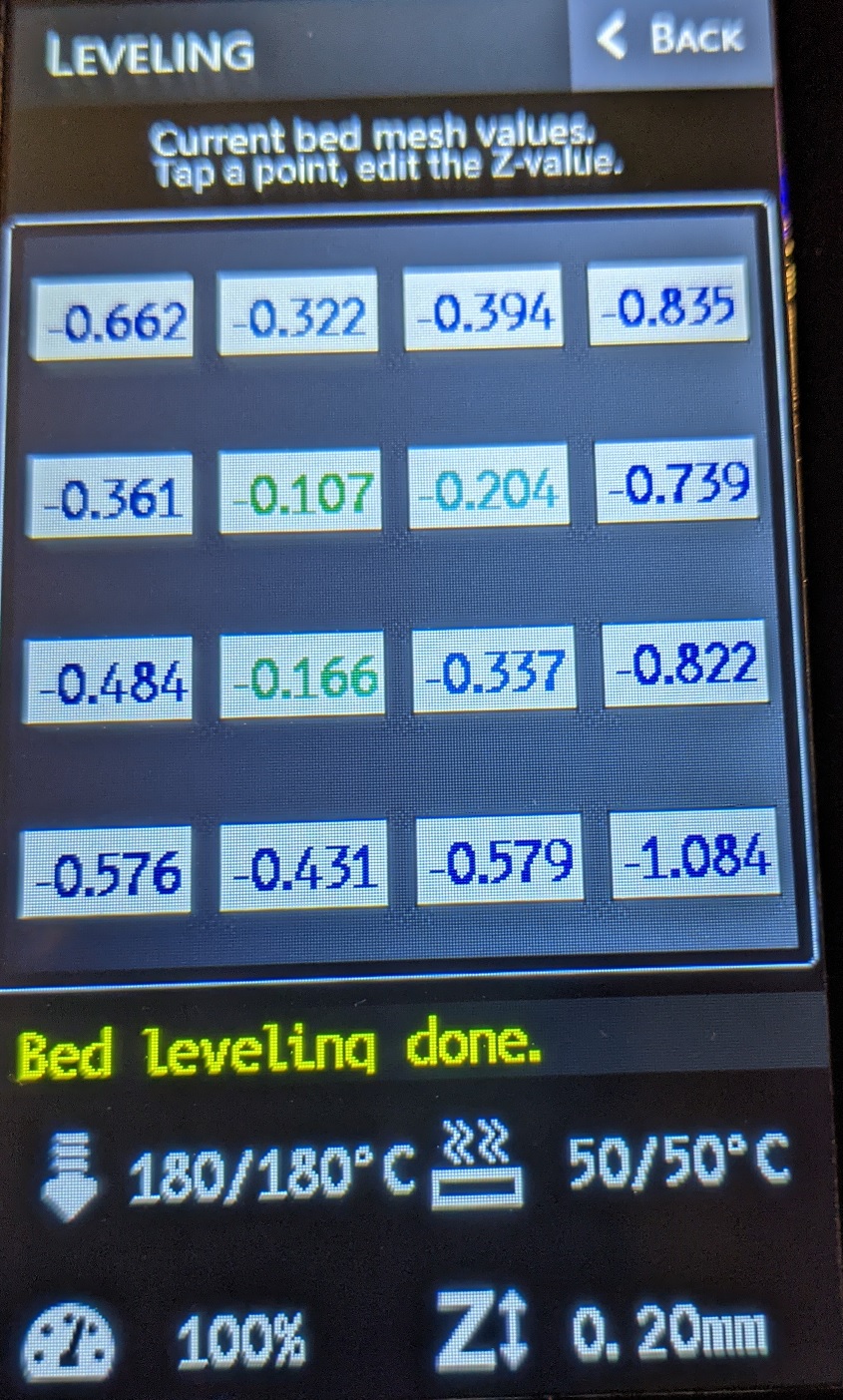
mesh.jpg


Test Print
TP.jpg
 
Is the extruder still the plastic arm one they've been dumping on all the Enders?
 
Honestly the ABL is really only for very minor adjustments. You still need to do a good job manually leveling it. If the surface itself is not level, then that’s a quality control issue. I personally use glass on all my printers and spend a fair amount of time making a good manual level before I use the ABL’s.
 
Is the extruder still the plastic arm one they've been dumping on all the Enders?

NO. This is a completely different animal. It's a clasp system (like the buckle on a tool box lid, for example) you unlock it, insert your filament through the extruder, then clamp it down. Simple as snot and works great.
 
Honestly the ABL is really only for very minor adjustments. You still need to do a good job manually leveling it. If the surface itself is not level, then that’s a quality control issue. I personally use glass on all my printers and spend a fair amount of time making a good manual level before I use the ABL’s.

Other than setting your baby z there isn't anything to do with leveling it. The bed is hard mounted with no leveling screws
 
So I have played around with the printer for a while now and I have some more observations:

The extruder is amazing. Best extruder I've ever used. Simple as can be. Can't say enough good things about it.

The build plate is friggin' MAGIC. Print. Let the part cool. Pick it up off the build plate. Not pry it up...Not use a scraper or razor blade to get a spot underneath it with a spatula.

Pick.
It.
Up.

Did I already say it's amazing, because it really, really is...Not exaggerating. Not even a little. It's that good.

It took a while to dial in the bed to get it level enough to print larger parts with confidence but it's working fine now...Had to shim a bit, but I'm happy with it.

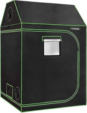
I bought one of these as an enclosure...just need to set it up
91M+7Q-jMxL._AC_SL1500_.jpg

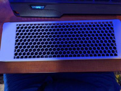
I have been too busy printing stuff with it to comment earlier but I'm starting my Computer case print with the left-hand 360mm Radiator mount.v

The part being printed (below) is using 4yr old 3d Solutec PLA filament so I don't expect perfection. It's bubbling and popping like pop corn right now but this is just a test of the design to see if everything lines up properly to secure the radiator...I can afford to waste some filament to test the design.

I have fresh spools of Overture Matte White and Matte Black, Overture PLA+ in White, and Overture ASA in White and Black for when I am ready to start the final printing of the parts. The mobo tray and SSD Mounts were easier than I thought. I just found some on TinkerCAD from some of my old designs and pasted them into the new design.

RightRad.jpg
 
The part above completed printing and while it came out relatively well I made some revisions to the design and am re-printing now.

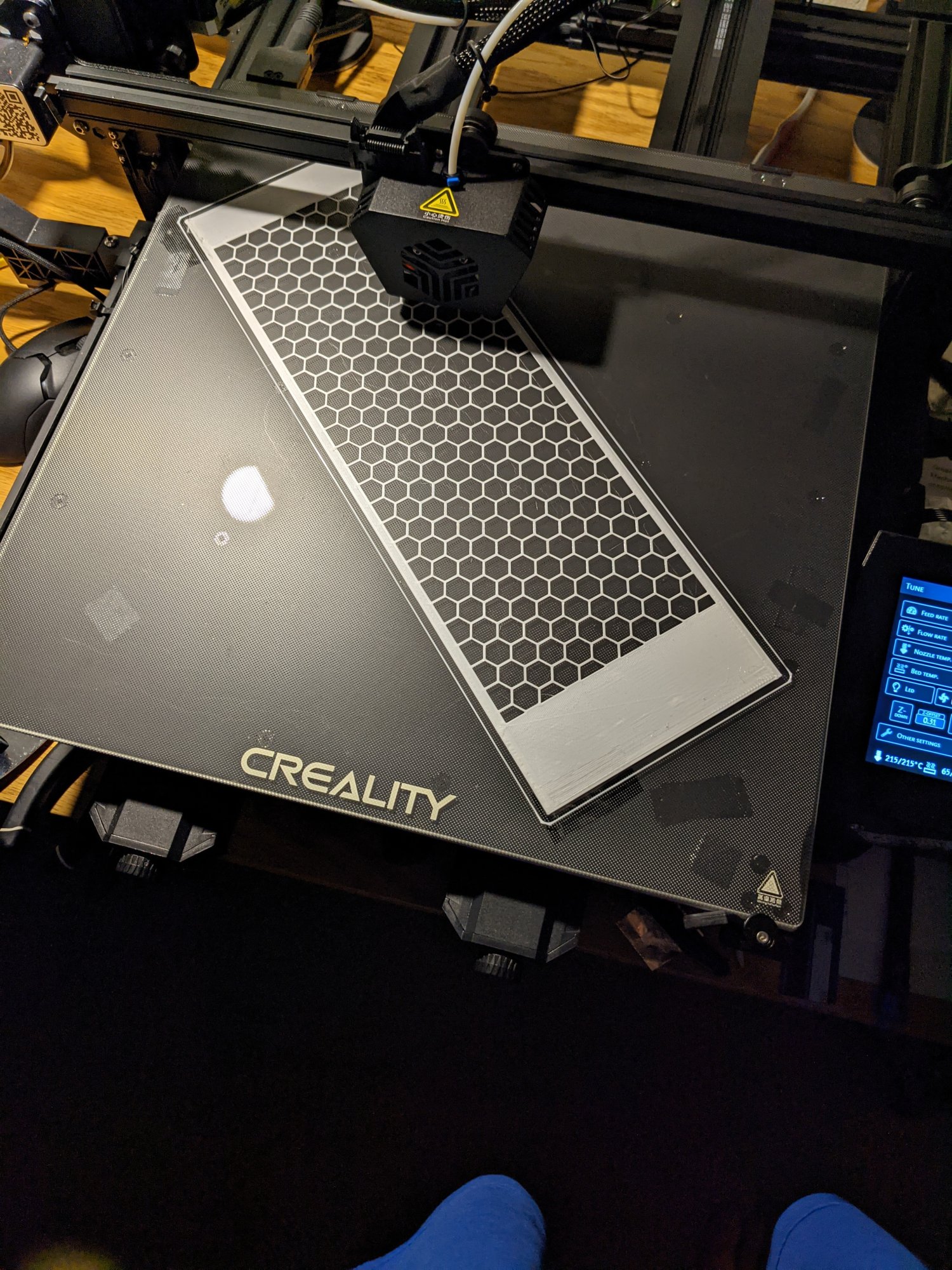
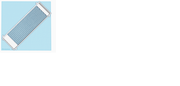
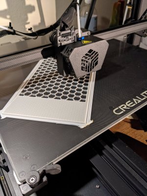
Keep in mind it's a 418mm x 135mm part being printed on a 400mm bed so I had to print diagonally. (and I removed my purge line from the GCode. More on that later.)

The part also had beveled edges and the original design had a small brim well offset from the part. The results?

Corners pulled up a bit since the heating area is a bit reduced outwards towards the edges even though I tried using tabs at the edges but they did not really help.
radmntfrnt.png
RadV1Done.jpg

The part still peeled up on the edges outwards at the far edges and I made the tabs a bit too thick so they're difficult to remove. (I'm no CAD CAM guy so half of my problems are the design...)

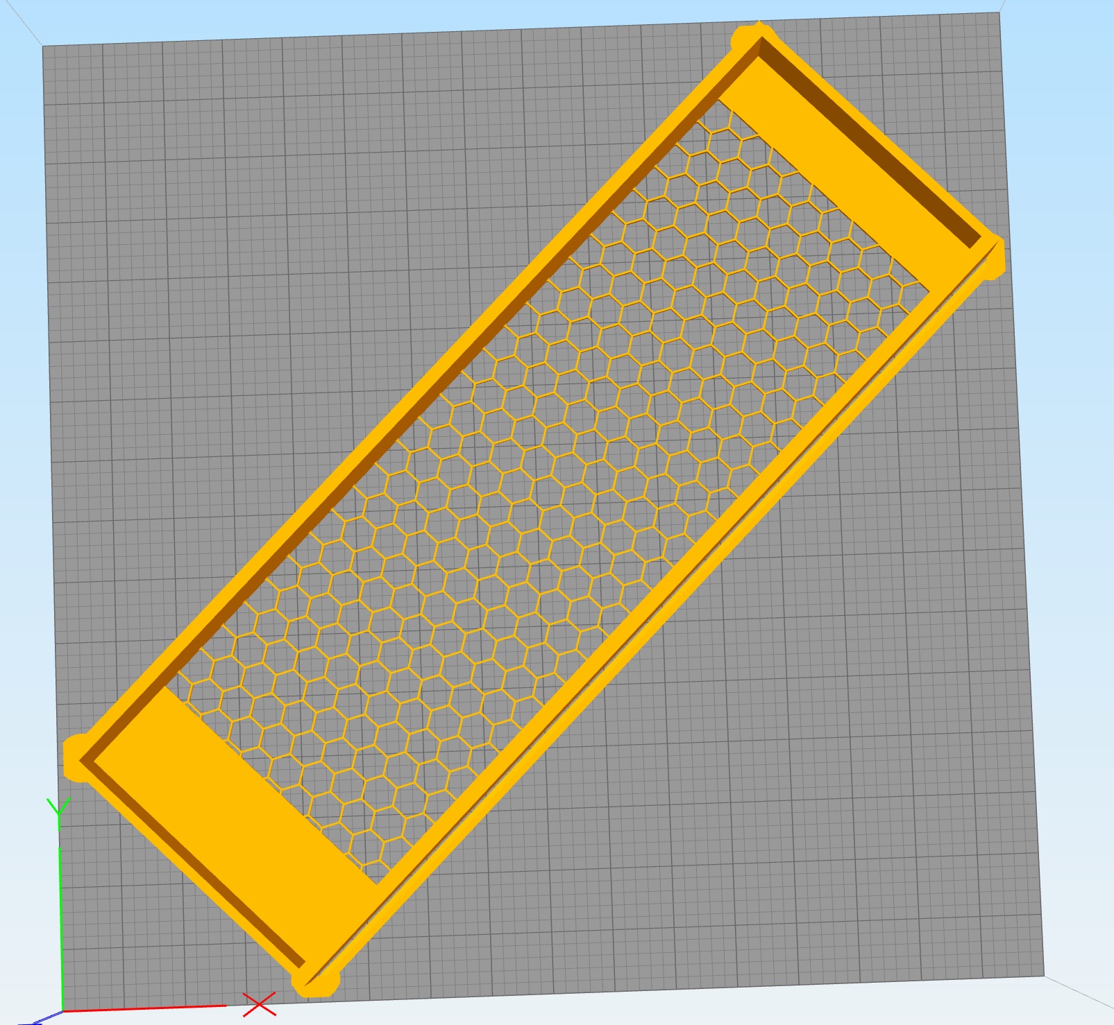
I then reoriented the part in the opposite direction left front to right rear versus the other way (necessitating the need to remove/move my purge line) and I came up with a decent design for a sacrificial brim to use. It's working well so far!

example.jpg


The sacrificial brim starts off 1mm thick and tapers as it nears the part. It's only .2mm where it attaches to the part so it'll be easy to remove and provides enough stability for the part so it doesn't curl

I cleaned the bed with 91% IPA and started the reprint at ~5pm and it's printing well now, though I had to baby it a bit when it started printing because there was no purge line to prime the print head. I'll be relocating/changing the style of the purge line so that it is primed well when it starts printing the other side Radiator mount.
RadReprint.jpg

The mobo tray is going to be a 3-part design which snaps together. The front and back panels will (should) be 1-piece parts, though they, too, will be pretty large.
 
If they givin' me 400x400 I'ma use it. (well...398x398 anyway)

Had a small amount of curling so Version 3 has a larger radius at the corners for some extra holding power. I also increased the length 1.25mm and reduced the thickness of the mesh from 5.9mm to 4mm for faster printing.

398x398.jpg


Time to make the doughnuts...(v.3 doughnuts but still doughnuts)
 
At work now so can't post pictures.

V3 came out nicely. Continuing with the rest of the design this week.

Suggestions on what mobo/CPU would be awesome. Don't need it to be high end...just want matx/mitx. Midrange would be best for this build
 
So I have played around with the printer for a while now and I have some more observations:

The extruder is amazing. Best extruder I've ever used. Simple as can be. Can't say enough good things about it.
Can you post pic of the extruder?
 
Interesting. It looks very much like their ender3 extruder just enclosed. Maybe that helps its rigidity enough.
 
Interesting. It looks very much like their ender3 extruder just enclosed. Maybe that helps its rigidity enough.
I think that is the case. It's a far better design than every other one I've ever used and I'm very happy with it.

The print bed could have been a bit more "even" but, other than that it's been a great printer thus far.
 
I think that is the case. It's a far better design than every other one I've ever used and I'm very happy with it.

The print bed could have been a bit more "even" but, other than that it's been a great printer thus far.
It does seem like a decent design. From creality I have a cr-10 and ender 3 both heavily modified but great printers even before that.

I appreciate the journey with the printer you are putting out here to read
 
Last edited:
It does seem like a decent design. From creality I have a cr-10 and ender 3 both heavily modified but great printers even before that.

I appreciate the journey with the printer you are putting out here to read
Yeah I had a CR-10S and a CR-10S4 before this one and thought I would give this one a shot. Glad I did. I already sold the 10S and will likely sell the 10S4 since this gives me the same capabilities.
 
Updating this thread with the additional issues I encountered so far.

1 -- The 400mm x 400mm heated bed does not heat evenly, making it a bit more difficult to print large parts without curling (418mm x 125mm Radiator shroud printed diagonally uses 398mm * 398mm of the bed. I had to make large sacrificial tabs and raise the bed temperature to minimize curling. Minimize, not "eliminate".

Solution: -- I removed the print bed and installed a layer of 2" x 1/8th inch plumbers pipe wrap on the bottom of the bed, and covered it with the 3M Metal tape used in HVAC. This reduced my heating time by about a minute from room temperature to 75°C and the edges of the bed now are much closer to the temperature of the center of the bed. The delta between the center of the bed and the edge used to be almost 15°C and it is only 4°C now. (I put 2 layers around the edges.)


2 -- The CR6Max doesn't have a floating bed which can be adjusted with "leveling screws". The bed is hard mounted to the carriage on silicone spacers, and "leveling" is done via the hot end, which is mounted to a strain gauge which creates a "mesh" by measuring 49 different points on the print bed. (Note: it only displays 16 data points on the screen)

The problem with this is that the spacers can be squashed if overtightened during assembly of that portion at the factory, or they can deform from heat cycles (Or BOTH). What I noticed was the spacers closest to the heating element on the bottom of the bed seemed to be a little more squashed than the others near the edge of the bed...

Solution: -- I purchased (4) 30CM aluminum tubes off Amazon for ~$15 and I will use a pipe cutter to create 25 spacers and disassemble the bed assembly (again) to replace the silicone bed spacers with aluminum tubing 6mm(od) with 4mm(id) ~13mm tall. This will allow me to fine tune the spacers for each of the 25 points and I can shim them with application of the afore-mentioned 3M Metal Tape as shims, or lap the newly-created spacer to adjust each of the mount points. I'm hoping to reduce the variation to within .05mm over all 400mm x 400mm
 
Have you considered an enclosure of sorts to reduce curling? Duct tape some cardboard boxes to fit around it and it see how that goes.
 
Have you considered an enclosure of sorts to reduce curling? Duct tape some cardboard boxes to fit around it and it see how that goes.
Sorry I haven't responded earlier. Had some stuff pop up which required my full attention.

The curling I've experienced is more due to the wide temperature fluctuation of the heated bed than using/not using an enclosure. The edges were upwards of 15°C cooler than the middle, so that had to be corrected first. The insulation of the heated bed has been completed. (3+ layers) and now the temperature delta between the center of the bed and edge of the bed is now less than 3°C.

I have already purchased a grow tent which is large enough to enclose the whole printer and the spool when hanging off the left side of the printer OR when mounted on the top of the printer. (Grow tent is 60"x60"x72")

The other thing I had to do (replace the bed mounts) has also been completed and, while the right edge of the bed is still out of whack (-.65, -.71, -.59, -.57) the rest of the bed is no greater than -.32 with most of the bed at -.104, -.109,-.140, -.120, -.139, etc

The bed mounts I got seem to be working VERY well to eliminate the leveling issue.

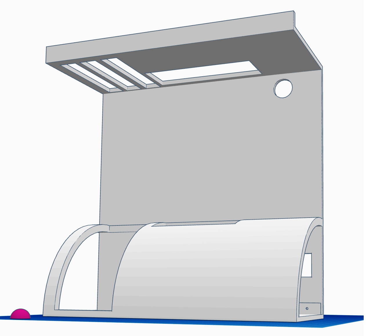
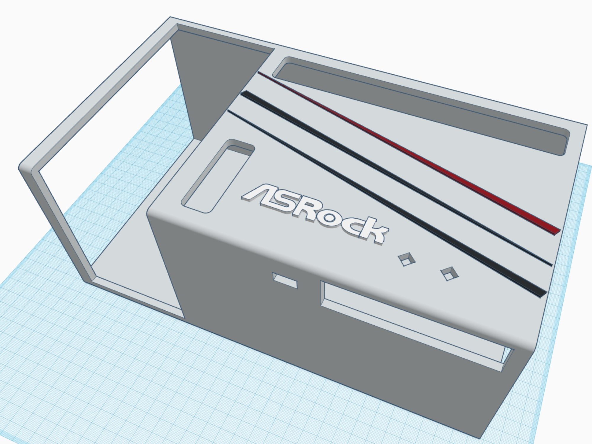
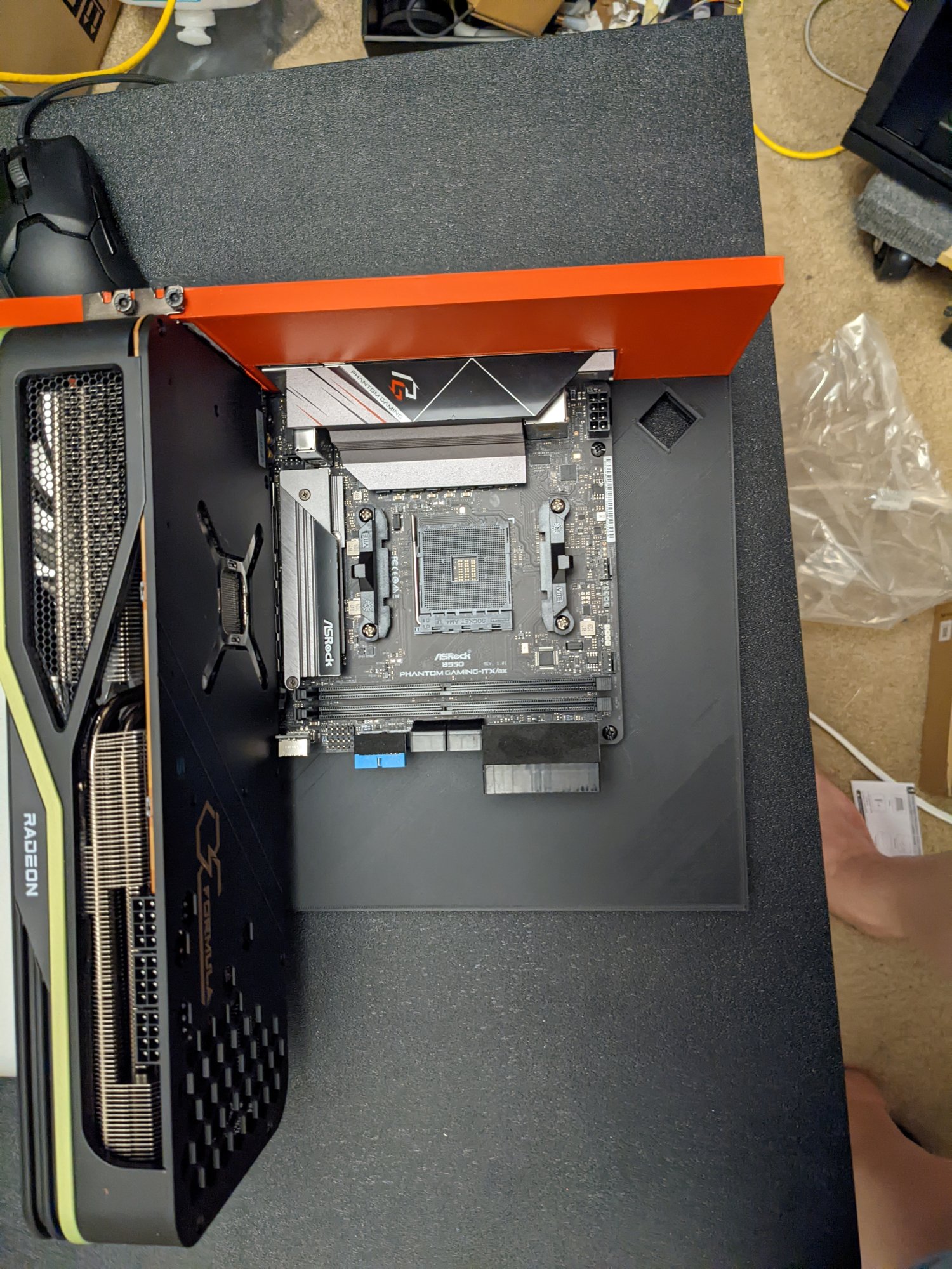
I am now prepping for my new ITX testbed/case print. (Ordering mobo and other accessories tonight) and will start the heavy design work once my new NAS arrives (I have to move all the data from my Lian Li O11 Dynamic XL to the new NAS so I can rip the lian li apart to use the CPU, RAM, SSDs and HDDs in the 3D printed case/testbed. the mock-up of the 3D printed case is below. The rounded part is pocketed to hold the Asrock OC Formula RX6900XT. PSU and one HDD mounted on the right back-side (and another HDD mounted on the bottom right side) to maintain balance so the thing doesn't tip over from the weight of the 6900XT. The case/test bench will be printed on its left side (less support needed that way)

Case.jpg
 
That's Way Too Big (tm) to print. Unless this is an assembled drawing.

Edit: Plus major weakness at the 90 degree at the top where there's like no material holding it together. External separately printed gussets are good. I'd print that in .... six or seven pieces.
 
That's Way Too Big (tm) to print. Unless this is an assembled drawing.

Edit: Plus major weakness at the 90 degree at the top where there's like no material holding it together. External separately printed gussets are good. I'd print that in .... six or seven pieces.
Nope. It's perfectly sized for what I need and more than strong enough for what I have planned.
 
That's Way Too Big (tm) to print. Unless this is an assembled drawing.

Edit: Plus major weakness at the 90 degree at the top where there's like no material holding it together. External separately printed gussets are good. I'd print that in .... six or seven pieces.

I am able to print the part in 1 piece (2.19lbs of a 2.2lbs spool) but your response piqued my interest over the weekend because printing it in sections opens up the possibility of printing in multiple colors...

I have left the original model intact but copied my tinkercad project to a new project and I broke it into 3 parts so I can print the back I/O panel in red, the mobo tray in silver and the bottom part in black to match the colors of the Asrock motherboard and video card.

Just an FYI...the reason the back panel won't break at the 90° angle is because the Asrock OC Formula RX 6900XT rests on the bottom plate...(so the vid card doesn't "hang") It puts zero pressure on that 90° bend.

I'll probably still print the 1-piece design because I really like the ability to do it in 1 piece but a 100+hr print job is hard to do unless I have a few days off work to be there to observe the process (in case there's a problem)
 
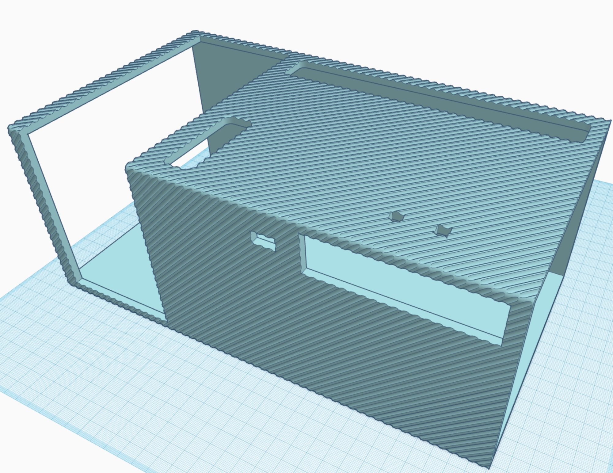
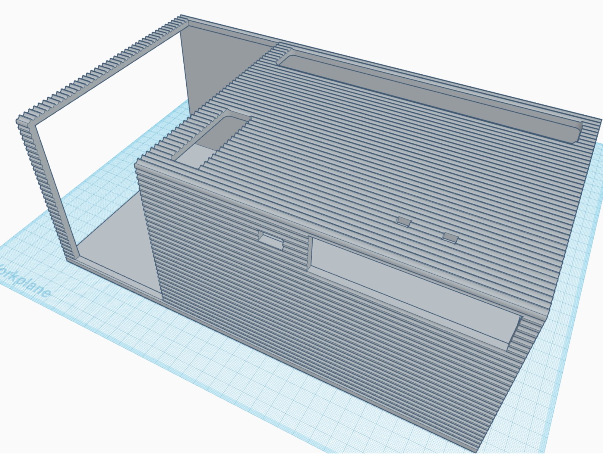
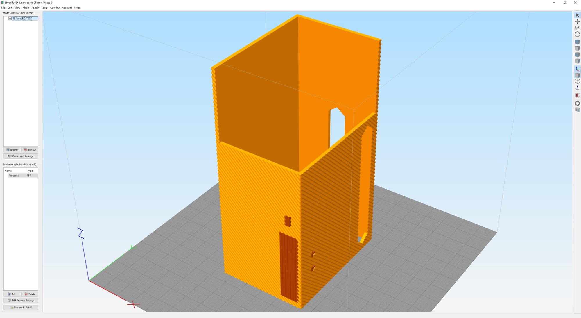
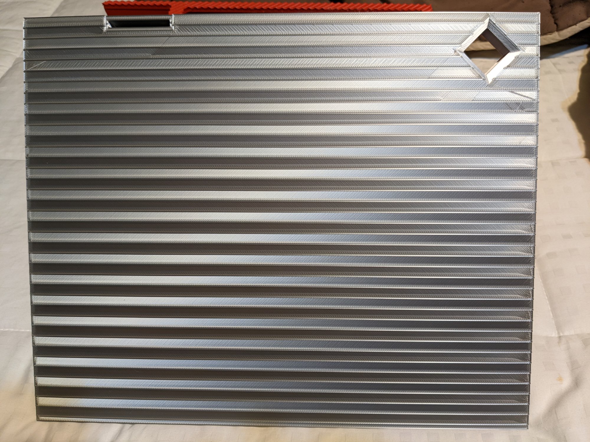
Working on some different designs for my 3D Printed case. What's your preference between these 3? Print times for each are within 2hrs and I plan to add the logos to all 3 since they match the mobo and video card

PlainCase.jpg

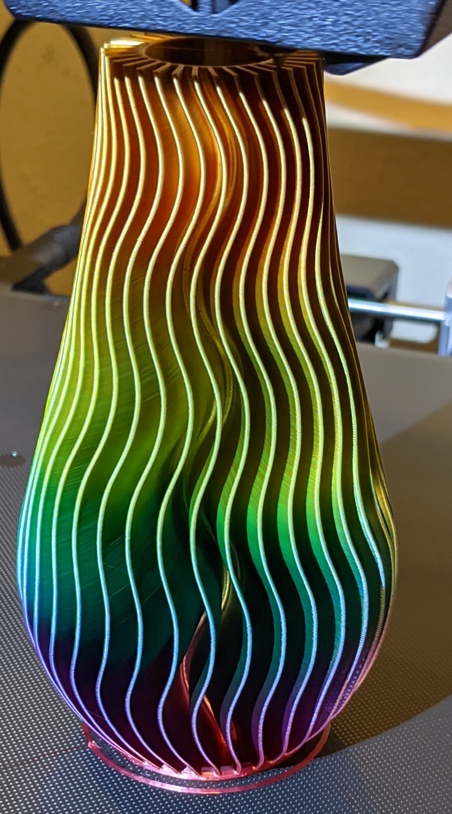
45Flute.jpg

StraightFlute.jpg
 
I like the 2nd one with diagonal lines, also most likely to hide layer lines really well
 
I'm partial to the 3rd one, those lines are hitting some specific retro notes
I like the 2nd one too
 
This is the mock up of the top and back. Going to do the back in matte black and the bottom part in silver. Need to order a new roll of silver. Mine is old and full of water, 😂
PXL_20211223_175924285~2.jpg
 
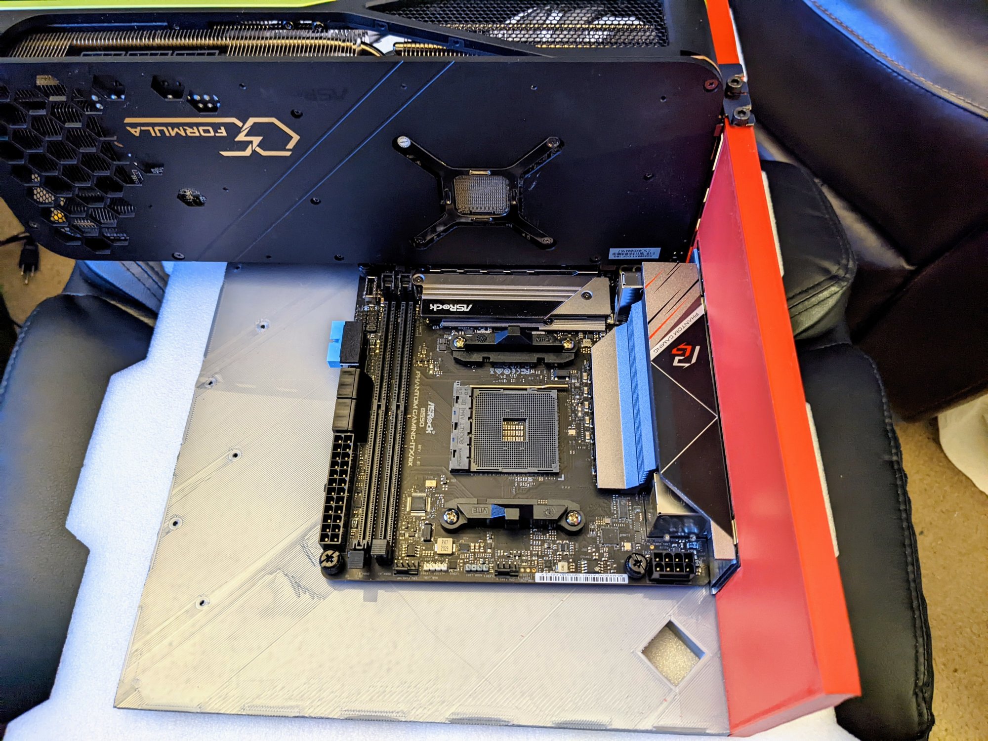
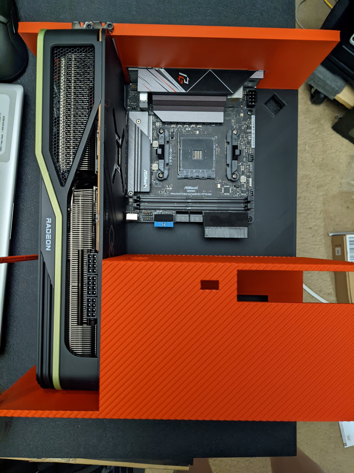
Here's the updated mobo plate installed. And, I'm only 1ft from completing the last part


PXL_20211226_021124173.jpg


PXL_20211226_020434458.jpg


Since it's a 58+ hour print I decided to go overboard to keep it from curling up. 😆
 
After 1D 11H 15M I'm at 62% and it seems fine so far.

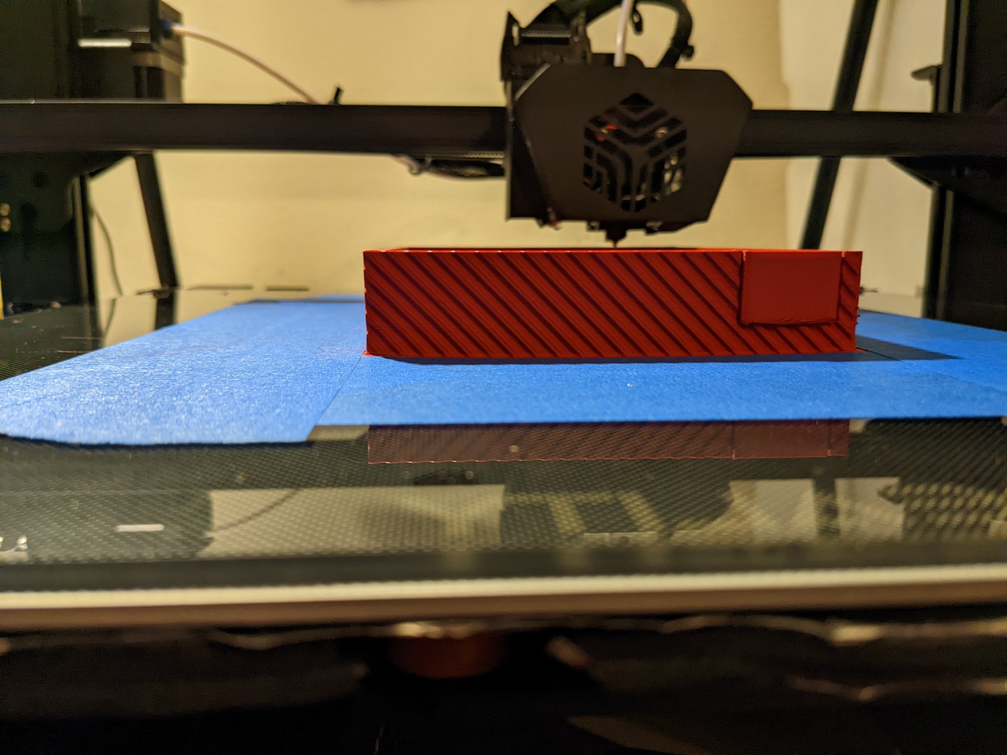
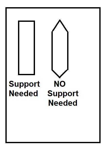
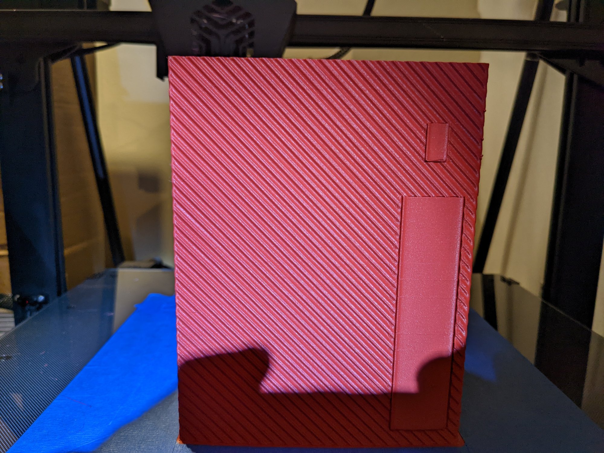
Of course, after 1D 11H 1M I figured a way to reduce the print time by 9hrs, lol. All I had to do was choose a different shape of the cable cut outs on the bottom part I'm printing from rectangle to use 45° angles because my printer can do 45° overhangs decently.
9hrs.jpg


Will edit for in progress pic in a sec.

Here's the progress so far
PXL_20211227_065252723.MP.jpg

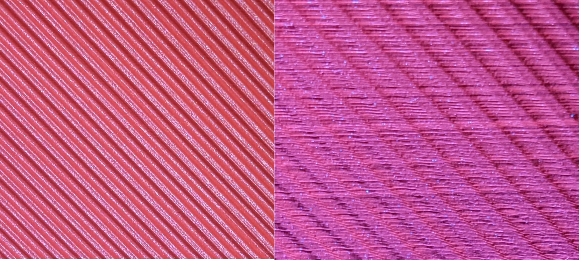
Here's the difference between Direct Lighting and Indirect Lighting. Same area of the print...
DirectIndirect.jpg
 
Last edited:
Very nice! i often get so astonished how good these things can be. Your case is looking good!
 
Bottom part is done after 64h38m (remember that this is a mock-up) and I am making some design changes then reprinting
PXL_20211228_104202918.jpg


New version looks like the pic below but takes only 44h 43m to print (gotta pick up my Silky Silver this afternoon after work)

64to44.jpg
 
Last edited:
My impressions are taking a nosedive. At least for now.

The printer kinda lost its mojo on the last part of the print of the red bottom part mockup and I couldn't figure out why. It was under extruding to the point that you could crush the left edge of the bottom case part with your fingers...

Couldn't for the life of me figure out what was going on until I decided to switch filament and noticed I couldn't feel the marks the extruder feed gear usually makes in the filament.

At that point I realized I'd have to tear down the "magical" extruder I raved about earlier to see what was going on.

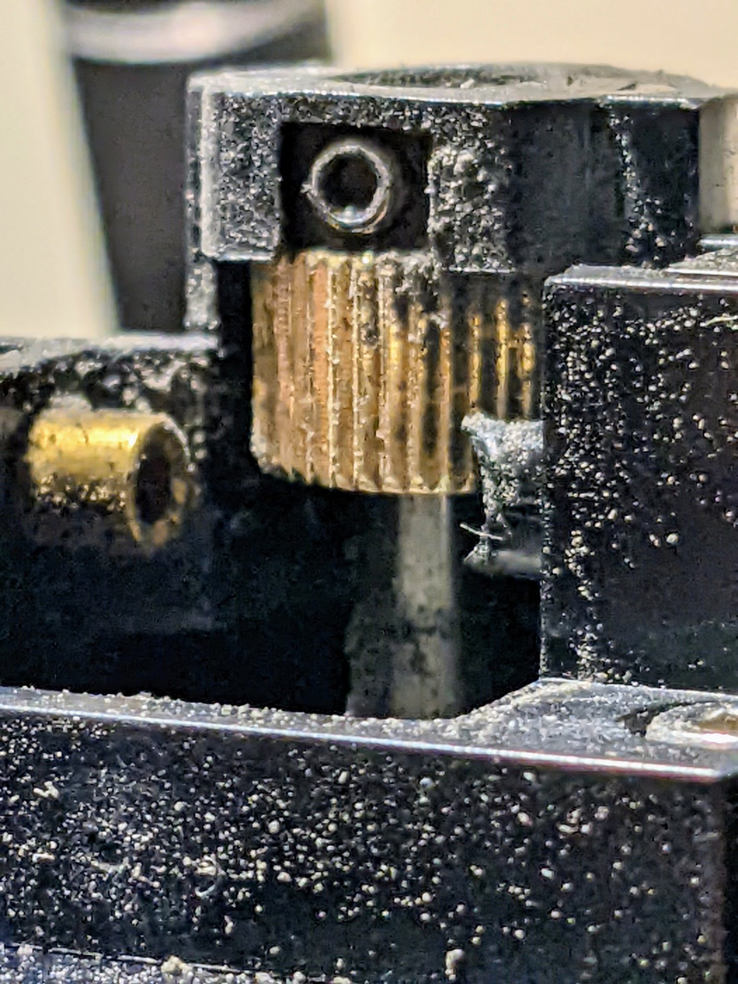
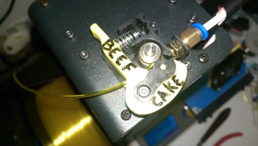
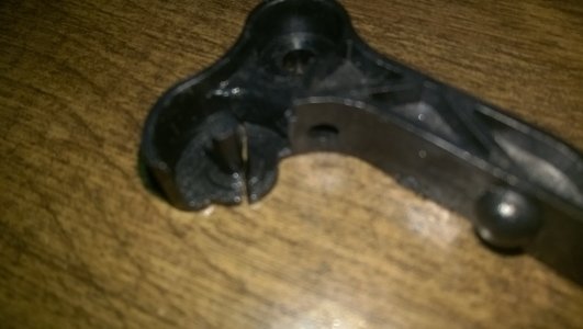
The grub screws holding the extruder feed gear came loose and the gear was pushed up to the point it was barely grabbing the filament. See pic below
PXL_20211230_083837306~2.jpg


I re-arranged it to be dead center of the feed path and tightened everything up and now it's extruding like someone is holding a gun to its head.

Printing part of a logo and some hard drive mounts and it seems to be working fine.

If you wanna know how to tear down the magical extruder, let me know...I am pretty much an expert at it now, lol
 
I am a personal big fan of bondtech bmg extruders, those things could could straighten metal coat hangers.

If it makes ya feel better this week I finished up my voron v0.1 and broke some of the extruder parts so it was held together with zip ties while it printed the replacement parts haha
 
Last edited:
I am a personal big fan of bondtech bmg extruders, those things could could straighten metal coat hangers.

If it makes ya feel better this week I finished up my voron v0.1 and broke some of the extruder parts so it was held together with zip ties while it printed the replacement parts haha
I held together the extruder arm with Zip Ties while I printed a newer, beefier version for my MonoPrice Select Mini V2 so I know what it's like...half the time you're printing "upgrades" for the printer your're printing upgrades on...The extruder on the CR-6Max was designed well, for a single gear extruder. They just didn't tighten either of the grub screws much (The first grub screw was loose enough to spin with your fingers and the second I could spin with no pressure on the allen wrench...)

IMAG0090.jpg
Beef Cake. Good Old Beef Cake...It's served me well.
Bad.jpg


EDITED TO ADD: The parts I printed after fixing the gear issue printed great. I'd post a pic but they're at home and I am at work after staying up all night working out what was wrong.
 
Last edited:
I held together the extruder arm with Zip Ties while I printed a newer, beefier version for my MonoPrice Select Mini V2 so I know what it's like...half the time you're printing "upgrades" for the printer your're printing upgrades on...The extruder on the CR-6Max was designed well, for a single gear extruder. They just didn't tighten either of the grub screws much (The first grub screw was loose enough to spin with your fingers and the second I could spin with no pressure on the allen wrench...)


Beef Cake. Good Old Beef Cake...It's served me well.

very true!!!

Ah makes sense, i don't think they loctite any of the grub screws either. a little blue goes a long way.
 
My impressions are taking a nosedive. At least for now.

The printer kinda lost its mojo on the last part of the print of the red bottom part mockup and I couldn't figure out why. It was under extruding to the point that you could crush the left edge of the bottom case part with your fingers...

Couldn't for the life of me figure out what was going on until I decided to switch filament and noticed I couldn't feel the marks the extruder feed gear usually makes in the filament.

At that point I realized I'd have to tear down the "magical" extruder I raved about earlier to see what was going on.

The grub screws holding the extruder feed gear came loose and the gear was pushed up to the point it was barely grabbing the filament. See pic below
View attachment 426820

I re-arranged it to be dead center of the feed path and tightened everything up and now it's extruding like someone is holding a gun to its head.

Printing part of a logo and some hard drive mounts and it seems to be working fine.

If you wanna know how to tear down the magical extruder, let me know...I am pretty much an expert at it now, lol
yo, this post saved me troubleshooting- thank you for sharing the info.
My E3v2 spit out an absolute garbage print on Wednesday and after fretting about it all night as I'm still a printing noob, I saw this post and turned out mine had the exact same issue. Tightened up the feed gear and it's running fine for now! Judging by the impressions on mine's extruder motor driveshaft, it looks like from the factory neither of the set screws on the gear were properly aligned with the key on the driveshaft, ack. Shoulda checked that when I built the thing :unsure:

Glad to help out. And, yes; It's definitely easier to check when you're building it...which is something I didn't do either so you aren't alone...

Mine's been running fine since tightening it back up but I do wish I'd thrown some lok-tite blue on the grub screws so they don't back out during another 68hr+ long print. I was out of lok-tite and it was 5am in the morning so I wasn't thinking straight, lol.

Almost finished with my mobo tray print "test" after 26hrs or so because there is a way that 3D printers handle printing gentle slopes (Think about printing a "wedge" and how it handles the rising slope...)

I wanted to see if I can leverage the way printers handle that scenario above to see if I can apply it to my motherboard tray as the top surface, so I did some stuff in Tinkercad to test if I can use that as a "surface finish".

Should be another 5-6hrs before I know for sure...will post a pic when I am done.

And now that I am thinking about the motherboard tray I have come up with a new idea...time to head over to Tinkercad to see if it's possible
 
This is the motherboard tray I was printing to see if I could leverage the way 3d printers handle wedge shaped items to use that as the "surface". It came out 99/100 IMHO. It's a shame it's obsolete now, lol.

Edited to add...It's a FLAT surface. I tilted the model to make the printer think it was a wedge.

PXL_20220102_041855789.jpg
 
GUESS WHO.

Guess who had a power outage 62hrs into a 68hr print?

Guess who was smart enough to shove enough UPS at his 3d printer to provide nearly 32 full minutes of uninterrupted power in case of a power outage because ain't nobody got time for a 68hr reprint?

Guess who had a FULL 32 minute power outage. *sigh*

Yes. I have the power outage protection in firmware. That only works if the power doesn't run completely out of the UPS then flickers 9 times as it comes back on...
 
Need to connect the EVGA PSU and load the operating system. And print the pwr/rst switches.

PXL_20220109_132434812.jpg
 
Had to do a factory reset on the printer today. 2nd one since purchase.

Seems fine now...odd though
 
Small update on this...

System problems prevented me from making much headway until recently. I managed to get a 5700G based system up and running to replace the dead 3950X and I got a 5800X system up and running to replace the 5950X system that died.

Troubleshooting is a PITA with a water cooled system and that's why it's taken me longer than I wanted (and why the progress on this has been slowed to a crawl)

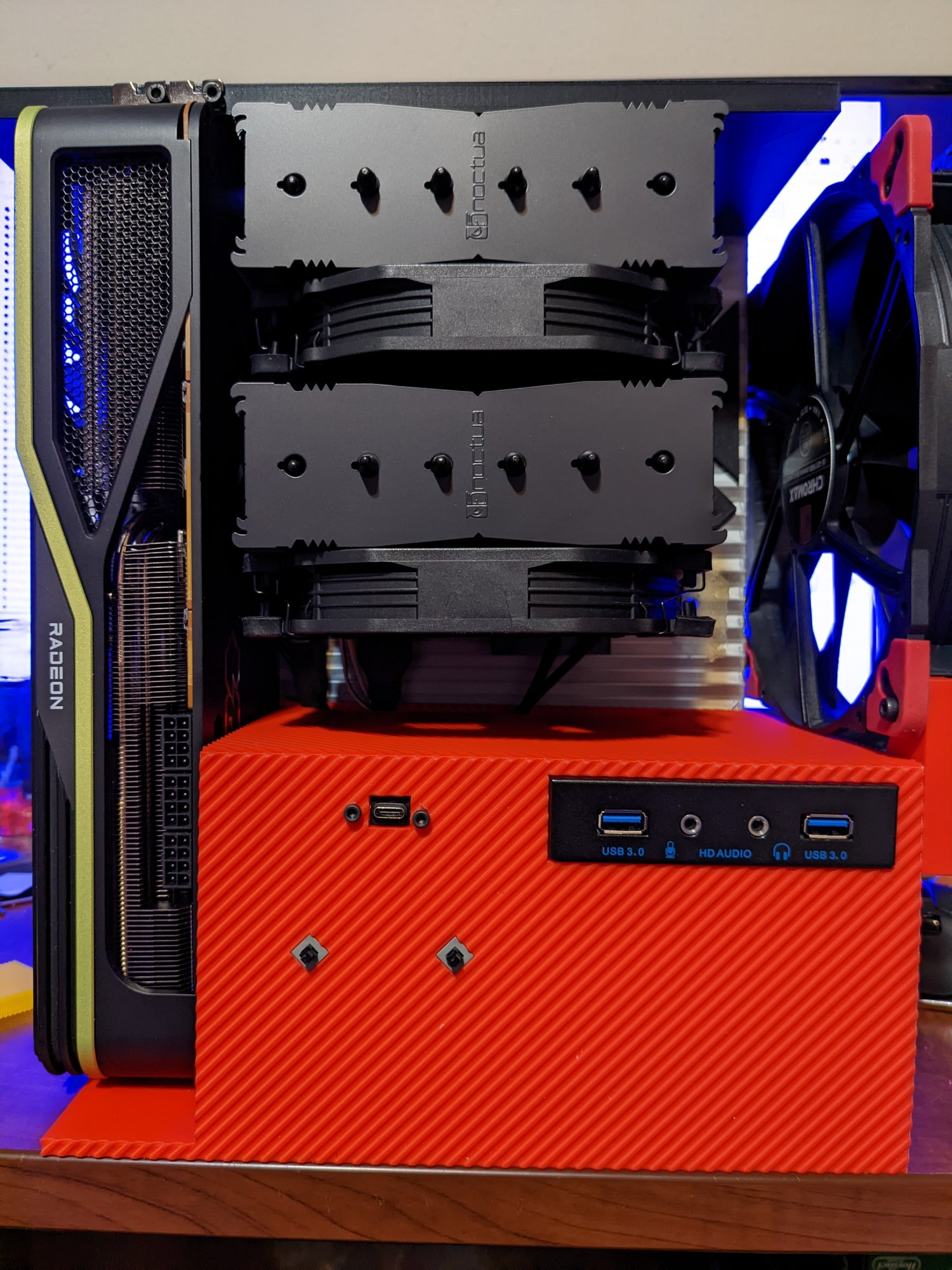
I have completed the process of printing my new 3D Printed case but I am in the middle of troubleshooting the 5950x/Liquid Devil 6900XT system so I have not yet had time to assemble the parts in the 3D Printed case. I don't doubt it will work, mind you...I just haven't had time to assemble it. I will post pics of the new case when I get a chance to take them.
 
Back
Top