Hi, New to the forum here. Hoping there's a graphics card repair expert out there that can point me in the right direction. I have a Vega 64 card that does not boot, and fan does not spin. After watching several youtube videos to gain an understanding of how the cards work I was hopeful I could revive it, but I'm stuck.
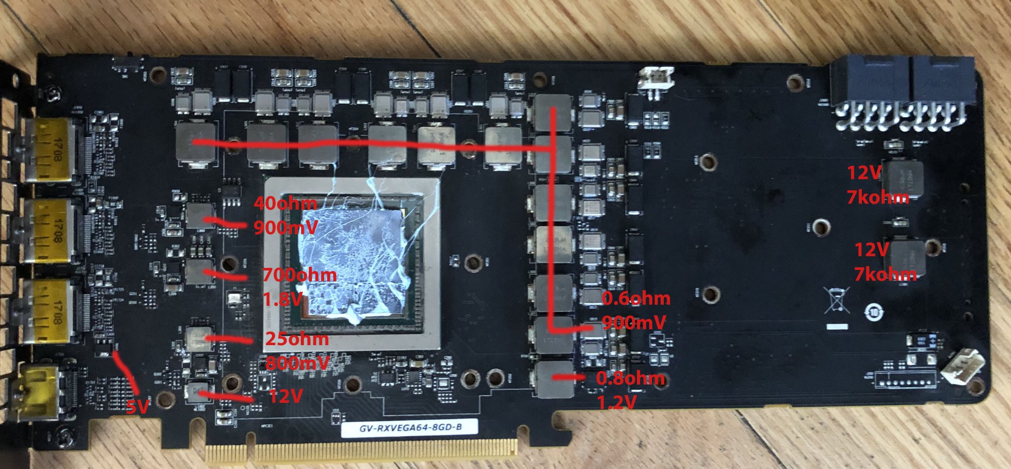
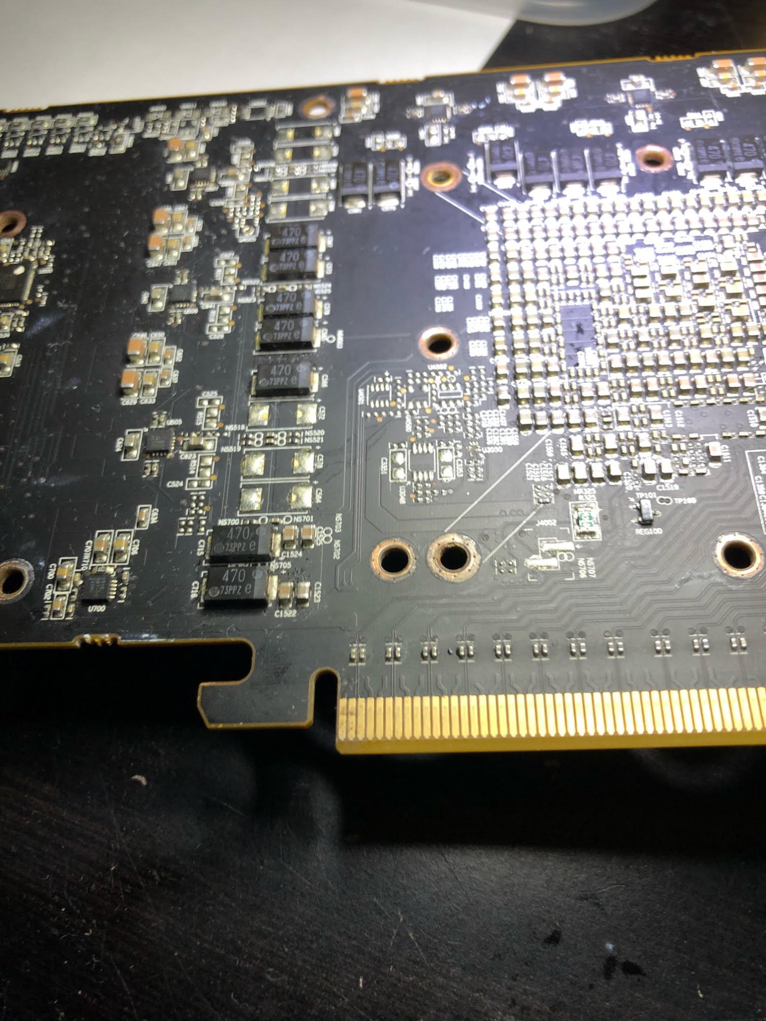
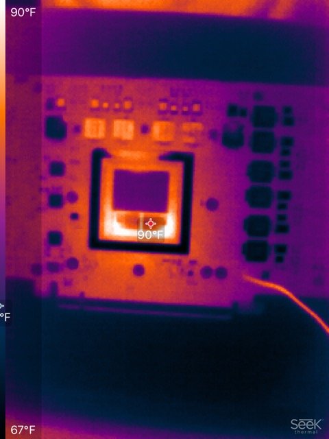
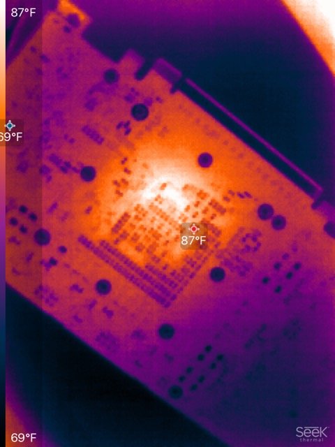
There doesn't seem to be a power short that I can find. When powered up the 12 phases are all getting 900mV, HBM is getting 1.2V, 5V rails are good on the front and back, PCIe rail has 800mV, Memory controller has 900mV. All the reading I took are in the attached image. The card gets hot, but fan does not spin, and no display out. Does anyone have any suggestions where I would look to continue troubleshooting?
Thanks!